Featured OEM Hardware & Precision Components
Explore our export-ready custom precision metal parts manufactured with tight tolerances and full material certification.
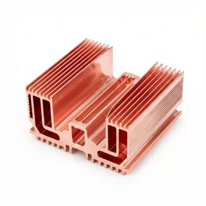
Custom High-Performance Copper Heatsink Products, Factories
View Product Details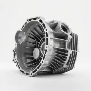
OEM Aluminum Die-Cast Transmission Housing Manufacturer, Product
View Product Details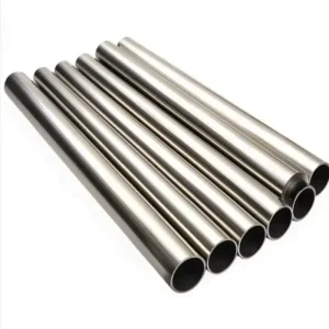
OEM Custom Precision Capillary Stainless Steel Pipe / Tube 1mm - 8mm | China Suppliers & Factory Supplier, Exporter
View Product Details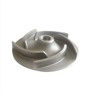
Custom High-Quality Stainless Steel Centrifugal Slurry Pump with Open Impeller - China Suppliers & Factory Product, Quotes
View Product Details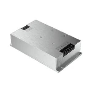
China Custom Aluminum Power Supply Enclosures Supplier, Products
View Product Details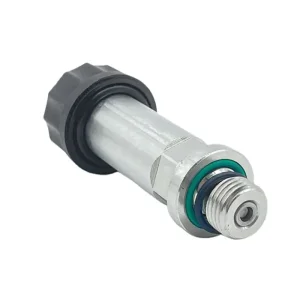
High-Quality High-Performance Hydraulic Solenoid Valve Core - Precision CNC Turned Excavator Parts from China Suppliers & Factory Exporter, Quotes
View Product Details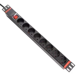
China Custom 8-Way German Standard 16A Rack-Mount PDU Power Strip - China Suppliers Factory Quality Quotes, Factory
View Product Details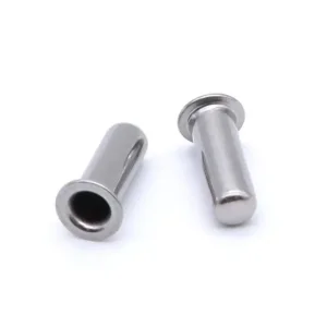
China Custom SS316 Deep Drawn Closed-End Flanged Sensor Housing for Temperature Probes (4mm OD) Manufacturers, Factories
View Product DetailsPrecision Sheet Metal Laser Cutting Engineering Overview
A rigorous industrial reference guide detailing thermo-optical cutting mechanisms, metallurgical structural integrity, and high-precision export manufacturing workflows.
In contemporary industrial manufacturing, Custom Sheet Metal Laser Cutting stands as the foundational pillar for rapid prototyping, complex geometry forming, and scalable OEM component production. As a leading manufacturer and direct global exporter located in Shenzhen, China, Shenzhen Sunmy Hardware Co., Ltd. bridges advanced photonics engineering with rigorous metallurgical discipline. Modern fiber laser technology has fundamentally redefined sheet metal fabrication by eliminating hard tooling costs, dramatically shrinking product launch timelines, and enabling unprecedented design freedom across stainless steel, aluminum, copper, brass, and high-strength alloy plates.
Unlike conventional mechanical stamping or CO2 laser systems, high-power solid-state fiber lasers operate at a optical wavelength of approximately 1.064 μm—roughly one-tenth that of a CO2 laser. This shorter wavelength yields an exceptionally high absorption rate in metallic substrates, particularly reflective materials such as copper and aluminum. Combined with high-dynamic CNC gantry motion systems, automated nesting algorithms, and high-pressure assist gas delivery (High-Purity Nitrogen vs. Oxygen), fiber laser cutting achieves narrow kerf widths, minimal Heat Affected Zones (HAZ), and burr-free edge qualities compliant with ISO 9013-1 standards.
Key Information Gain Benchmark: Fiber vs. CO2 & Mechanical Punching
Fiber laser cutting delivers 3x higher wall-plug energy efficiency compared to legacy CO2 resonators. When processing thin-to-medium gauge sheet metals (0.8mm to 6.0mm), fiber laser processing speeds exceed CNC mechanical turret punching by up to 400% while maintaining zero tool wear, zero edge deformation, and zero custom die capital expenditures.
Technical Matrix: Laser Wattage, Gas Assist & Dimensional Tolerances
To assist procurement managers, mechanical engineers, and hardware architects in selecting the optimal cutting parameters, the following empirical data matrix highlights our standard fabrication capabilities across various metal grades:
| Material Substrate | Thickness Range | Assist Gas Type | Cutting Speed (m/min) | Kerf Width (mm) | Standard Tolerance |
|---|---|---|---|---|---|
| Stainless Steel (304 / 316L) | 0.5 mm - 12.0 mm | High-Purity N₂ (20 Bar) | 2.5 - 28.0 | 0.12 - 0.25 | ± 0.02 mm |
| Aluminum Alloy (5052 / 6061-T6) | 0.8 mm - 16.0 mm | Nitrogen / High-Air | 3.0 - 32.0 | 0.15 - 0.30 | ± 0.03 mm |
| Carbon Steel (SPCC / Q235) | 1.0 mm - 25.0 mm | O₂ Exothermic / N₂ | 1.2 - 22.0 | 0.18 - 0.40 | ± 0.05 mm |
| Pure Copper (C1100) & Brass (C2680) | 0.5 mm - 8.0 mm | High-Purity N₂ | 1.8 - 18.0 | 0.10 - 0.22 | ± 0.03 mm |
| Titanium (Gr1 / Gr2 / Ti-6Al-4V) | 0.5 mm - 6.0 mm | High-Purity Argon (Ar) | 1.0 - 12.0 | 0.08 - 0.18 | ± 0.02 mm |
Tailored Engineering Solutions for High-Tech Sectors
Providing precision laser-cut sheet metal sub-assemblies across demanding industrial verticals worldwide.
Aerospace & Defense Structural Panels
Fabrication of ultra-lightweight titanium and 7075-T6 aluminum brackets, airframe mounting shims, and high-frequency internal structural partitions with tight weight-budget control and AS9100D compliance traceability.
Semiconductor Equipment & Wafer Handling
Electropolished SS316L cleanroom chassis panels, vacuum chamber covers, and high-precision aluminum wafer carriers requiring zero particulate contamination and micron-level surface flatness (Ra < 0.4 μm).
EV Battery Packs & Energy Storage (ESS)
Custom laser-cut and nickel-plated copper busbars, aluminum cell interconnections, thermal management cold plates, and structural battery box enclosures designed for vibration tolerance and electrical isolation.
Data Center Servers & Power Modules
Precision rack-mount PDU chassis, server drawer enclosures, EMI/RFI shielding covers, and high-efficiency fan mounting baffles executed with automated press brake bending and Pemnut hardware installation.
Medical Device Enclosures & Diagnostics
Autoclavable stainless steel probe housings, diagnostic equipment chassis, and laser-welded capillary tube assemblies meeting stringent FDA, ISO 13485, and medical-grade biocompatibility standards.
Industrial Robotics & Automation Actuation
Complex 3D articulated arm mounting plates, sensor brackets, timing belt pulleys, and heavy-duty motor end bells engineered to withstand high dynamic shear stress and cyclic fatigue load.
Global Supply Chain & Sourcing Cost Economics
Evaluating total cost of ownership (TCO), nearshoring risks, and the strategic advantages of China's direct factory export ecosystem.
In today's volatile global supply chain landscape, procurement directors face a critical tradeoff between local nearshoring speed and direct factory cost efficiency. Sourcing Custom Sheet Metal Laser Cutting products from accredited exporters in Shenzhen, China delivers substantial cost advantages without compromising precision or structural integrity.
By leveraging an end-to-end local supply cluster, raw sheet materials—such as mill-certified SS316L, AL5052-H32, and oxygen-free high-conductivity (OFHC) copper—are sourced within hours from accredited steel mills. Coupled with low-overhead continuous fiber laser automation, total landed procurement costs are frequently 35% to 50% lower than domestic European or North American job shops.
Total Cost of Ownership (TCO) Comparison Framework
Below is a quantitative operational breakdown demonstrating how direct factory laser cutting integration optimizes budget allocation across product lifecycle phases:
| Cost Factor / Evaluation Phase | Western Domestic Job Shops | Sunmy Direct Export Model | Strategic Business Advantage |
|---|---|---|---|
| Tooling & NRE Expense | High ($5,000 - $25,000 for hard dies) | $0 NRE (Laser Direct Cut) | Zero upfront capital required for complex geometries |
| Nesting Material Yield | 65% - 75% Manual Nesting | 88% - 94% AI Nesting | Maximum sheet utilization lowers unit part cost |
| Design Iteration Lead Time | 2 - 4 Weeks per Revision | 24 - 48 Hours DFM Turnaround | Accelerated NPI (New Product Introduction) cycles |
| Quality Verification | Standard Sampling Batch Inspection | 100% CMM & FAI (AS9102) | Eliminates incoming inspection bottlenecks at destination |
| IP & Data Security | Broker / Third-Party Hand-off | Strict Direct Factory NDA | Complete protection of CAD drawings & proprietary specs |
Engineering Rules for Precision Sheet Metal Fabrication
Essential design guidelines to maximize manufacturability, minimize distortion, and optimize unit yield.
1. Minimum Feature Size & Hole Diameters
As a rule of thumb, laser cut hole diameters (D) should never be smaller than the sheet thickness (T), i.e., D ≥ T. For high-precision stainless steel or aluminum, ratios down to D = 0.8T are achievable using pulse-laser pierce cycles. Sub-thickness holes risk thermal blowout and internal kerf taper.
2. Hole-to-Edge Distance Ratios
To prevent bulging or structural tearing during secondary CNC press brake bending operations, holes must be positioned at a distance (H) of at least 2.5T + Inside Bend Radius (R) from the bend line. If geometry forces closer placement, relief slots should be incorporated into the laser nesting file.
3. K-Factor & Bend Relief Specifications
Accurate laser blank development requires precise K-factor calculation based on material yield strength and die opening width. Standard K-factors applied: 0.33 for soft aluminum and 0.42 to 0.45 for stainless and mild steel. Bend relief cutouts must have a width (W) ≥ T and depth (D) ≥ T + R.
4. Surface Finishing & Secondary Operations
Post-laser fabrication includes automated deburring, vibratory tumbling, PEM fastener insertion, TIG/MIG laser welding, sandblasting, anodizing (Type II & Class 2 Type III Hardcoat), powder coating (Ral color matching), and passivation per ASTM A967 standards.
Rigorous Inspection & Regulatory Protection
Ensuring every exported shipment complies with international engineering standards and environmental mandates.
3D CMM & Optical Scanners
All finished parts undergo dimensional validation using high-precision Hexagon CMMs and 2D optical laser profilers, verifying position tolerances down to ±0.005 mm.
AS9102 First Article Reports
Full FAI documentation provided with initial production lots, including raw material heat numbers, spectrographic analysis, and bubble drawing dimension mapping.
RoHS, REACH & ISO 9001
100% compliant with EU RoHS 3 (Directive 2015/863) and REACH SVHC requirements. Operating under ISO 9001:2015 and IATF 16949 certified quality management protocols.
Next-Generation Fiber Laser Innovations
Pioneering ultra-high power photonics, AI-driven adaptive optics, and automated zero-emission laser cutting cells.
30kW+ Ultra-High Power Resonators
Transitioning to 30kW and 60kW fiber laser sources enables thick plate processing (up to 50mm stainless steel) with air/nitrogen assist, eliminating slag, reducing taper angle, and lowering electrical consumption per cut meter by 60%.
AI Adaptive Beam Shaping & Autonomous Nesting
Integrating real-time closed-loop optical feedback sensors that dynamically adjust beam diameter, focal position, and gas pressure mid-cut. Automated AI vision systems inspect edge kerf quality live on the cutting bed, preventing batch defects.
Frequently Asked Questions by Industrial Buyers
Comprehensive engineering clarity regarding tolerances, minimum orders, lead times, and custom sheet metal capabilities.
What standard dimensional tolerances can your laser cutting systems achieve?
Our high-precision CNC fiber laser cutting systems consistently hold linear profile tolerances of ±0.01 mm to ±0.03 mm for sheet thicknesses up to 3.0 mm, and ±0.05 mm for heavy plate up to 20.0 mm, adhering to ISO 2768-mK and ISO 9013 Class 1 standards. Hole-to-hole center distance tolerances are held within ±0.02 mm.
Why choose Nitrogen assist gas over Oxygen when laser cutting stainless steel?
High-pressure Nitrogen (N₂ at 16 to 24 Bar) acts as a high-velocity shielding inert gas that vaporizes the molten metal without exothermic oxidation. This prevents oxide layer formation on stainless steel cut edges, resulting in a bright, silver, burr-free edge ready for direct welding or powder coating without secondary grinding.
What is your Minimum Order Quantity (MOQ) for custom prototype laser parts?
We support engineering flexibility with an MOQ of 1 piece for rapid prototype evaluation. Because fiber laser cutting requires zero custom hard tooling, prototyping costs remain extremely low. Once design verification is completed, we seamlessly scale to mass volume supply.
How do you protect customer IP, CAD files, and technical drawings?
We execute legally binding Non-Disclosure Agreements (NDAs) prior to file transfer. All 3D STEP/IGES and 2D DXF/DWG drawings are encrypted and restricted solely to authorized engineering staff. As a direct factory manufacturer, your proprietary designs are never shared with external brokers or third-party suppliers.
What quality control documentation is delivered with export shipments?
Every shipment can include full quality packages: Material Test Reports (MTR per EN 10204 3.1), CMM Full Dimensional Inspection Reports, First Article Inspection (FAI per AS9102), RoHS/REACH certificates, and Coating Thickness / Salt Spray Test Reports upon request.
What CAD formats do your automated nesting systems accept?
Our CAM nesting software natively accepts 3D files in STEP (.stp), IGES (.igs), SolidWorks (.sldprt), and Parasolid (.x_t) formats, as well as 2D flat vectors in DXF and DWG formats. If only physical samples or 2D PDF drawings exist, our engineering team can reverse-engineer the parts into CAD geometry.
Precision Engineering Solutions & Assemblies
Explore our specialized custom hardware manufactured to strict global engineering standards.
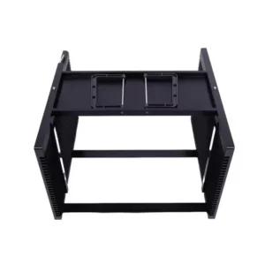
Custom Premium 8-Inch CNC Machined Aluminum Semiconductor Wafer Carriers from China Suppliers and Factory Manufacturer, Supplier
View Product Details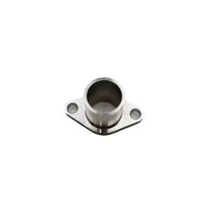
Custom Premium Custom Stainless Steel Casting Services for Water Valves, Impellers & Pipe Fittings from China Suppliers and Factory Service, Product
View Product Details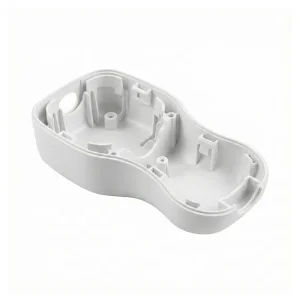
China Custom Medical Device Housing Suppliers, Service
View Product Details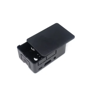
High-Quality Custom Injection Molded Electronics Enclosure | OEM Project Box Manufacturers, Factories
View Product Details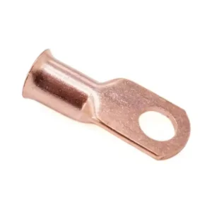
Custom Custom Tinned Copper Lug Ring Crimp Terminal Battery Wire Connector from China Suppliers & Factory Manufacturers, Exporters
View Product Details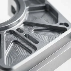
China Lightweight Aerospace Structural Components from Reliable China Suppliers and Factory Supplier, Service
View Product Details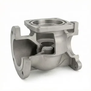
Custom China Stainless Steel Valve Body - Investment Casting Suppliers | Reliable Factory Solutions Supplier, Quotes
View Product Details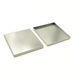
OEM Custom Stamped PCB EMI / RFI Shielding Covers Exporters, Factory
View Product DetailsReady to Accelerate Your Precision Sheet Metal Manufacturing?
Send us your 3D CAD files (STEP, IGES) or 2D vector drawings (DXF, DWG). Our senior application engineers will evaluate your design for laser cutting, bending, and surface finishing, returning a detailed DFM feedback report and factory-direct quote within 24 hours.