OEM Custom Stamped PCB EMI / RFI Shielding Covers Exporters, Factory
Product Description
Product Overview
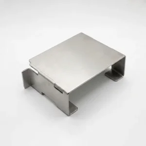
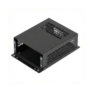
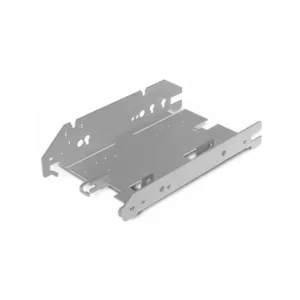
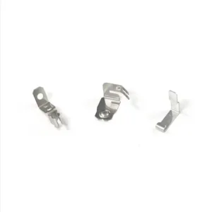
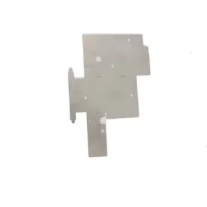
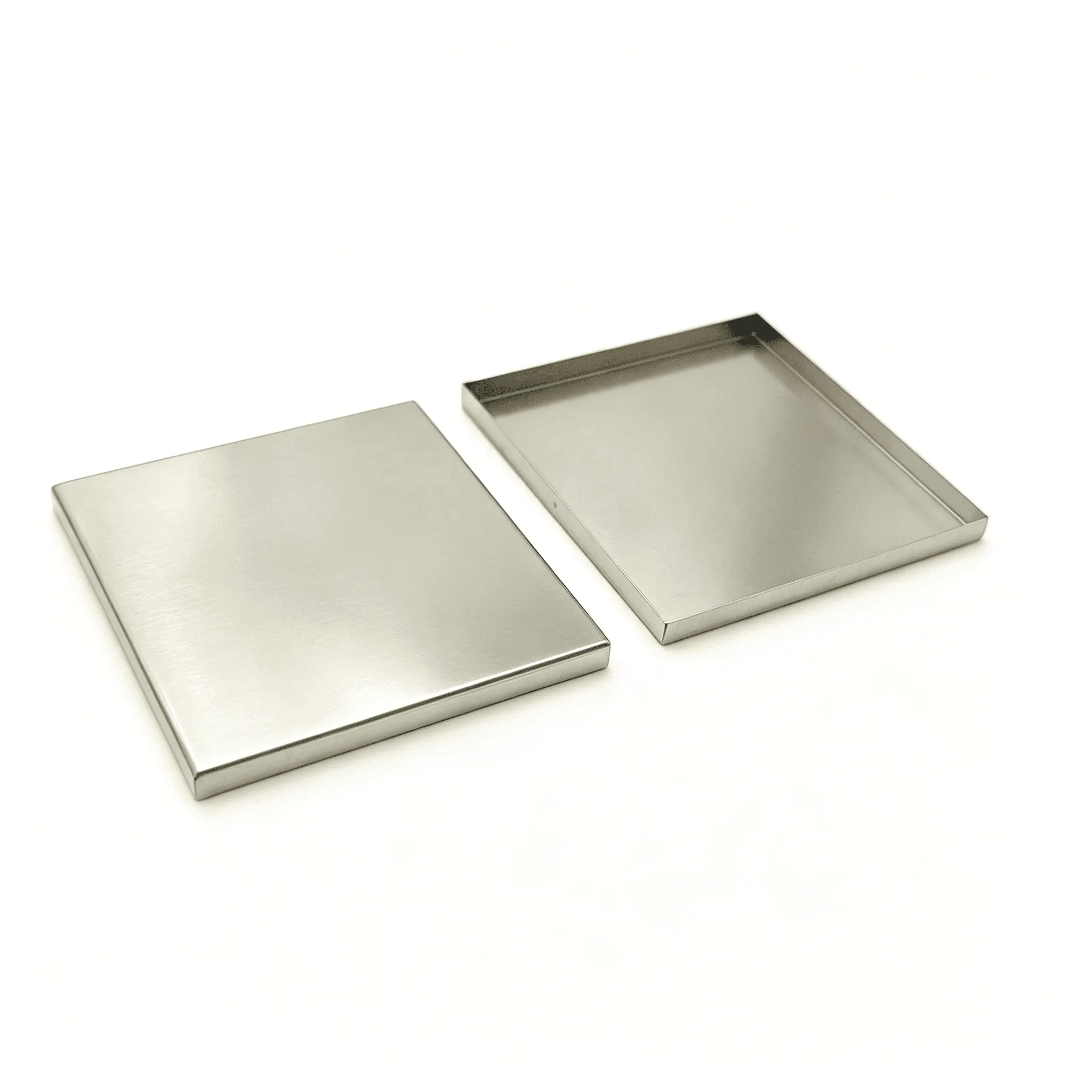
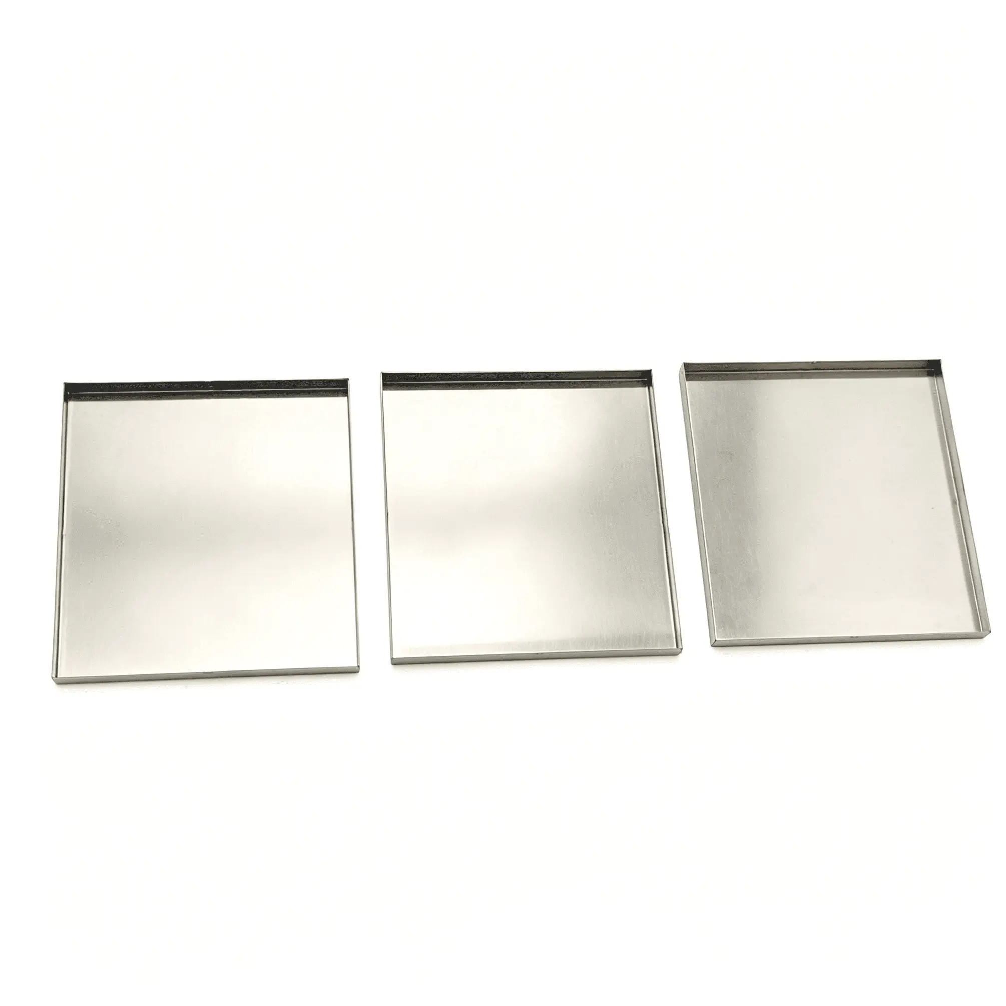
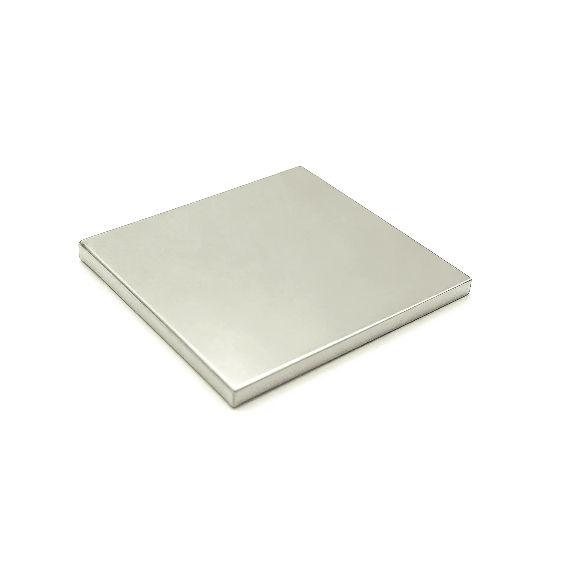
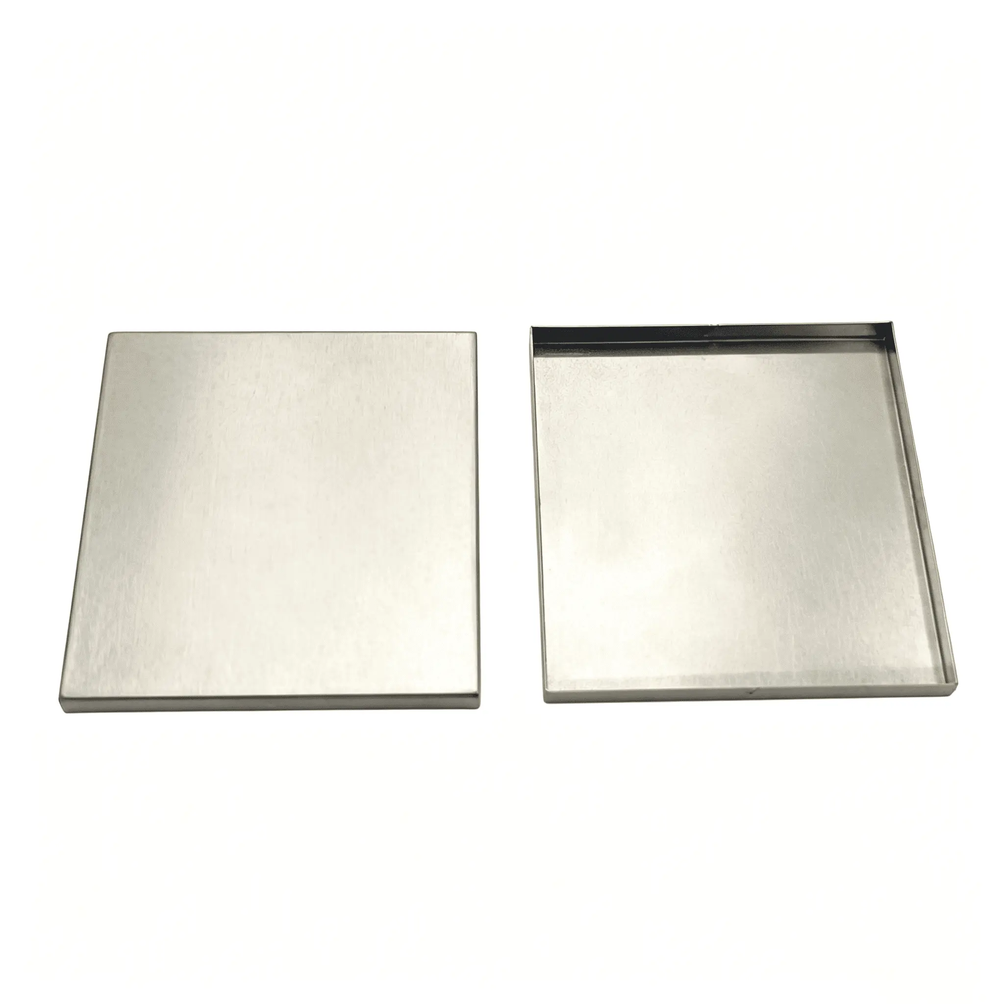
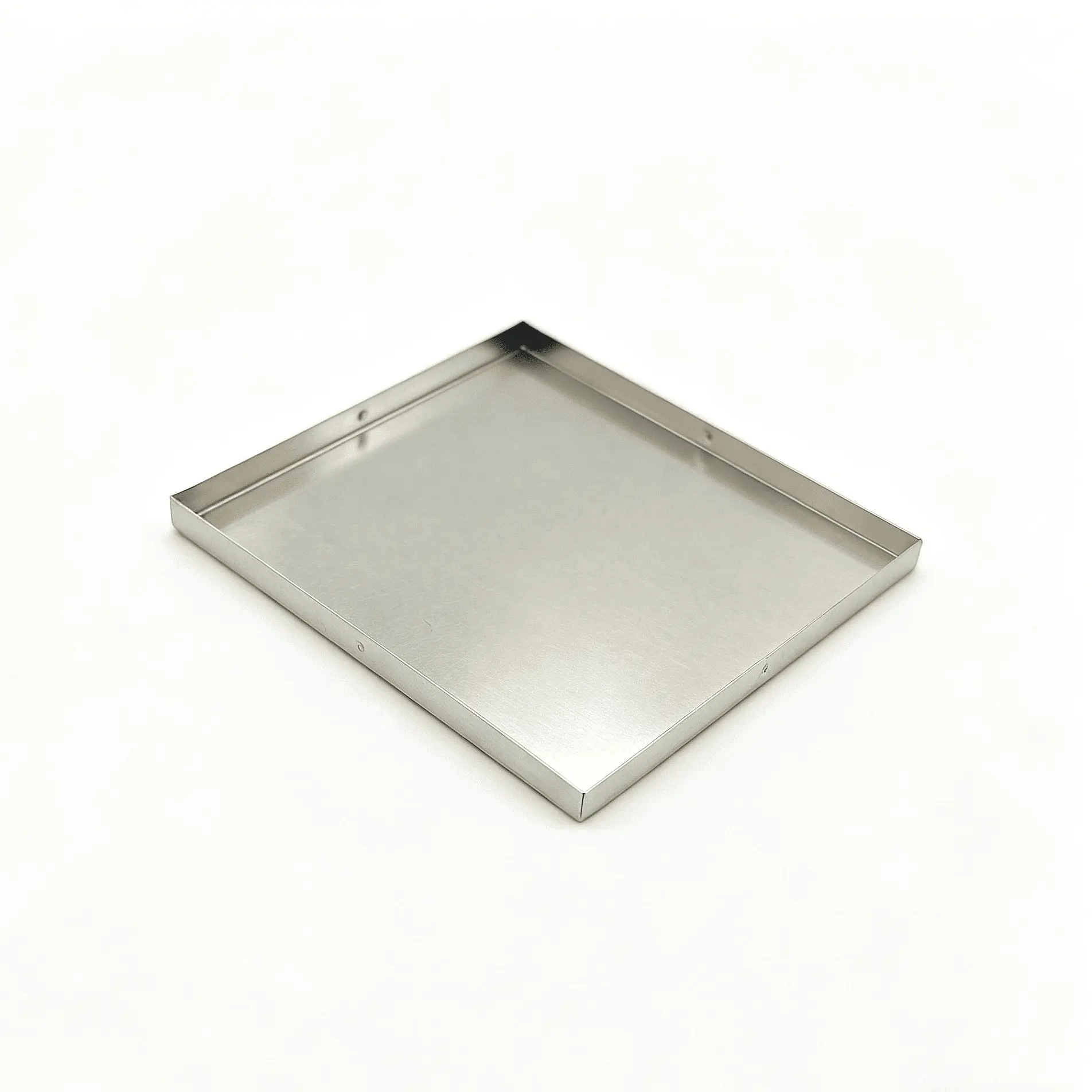
Keep your PCB layout. Customize the shield around it. Shenzhen Sunmy Hardware Co., Ltd. manufactures EMI / RFI shielding covers and cans to customer drawings or samples. Footprint, wall height, sheet thickness, corner details, retention features and finish can be tailored to your assembly. The illustrated parts are shallow, open-bottom covers; mating frames and clips are not assumed to be included. Start with prototypes, then scale the approved configuration into repeat production.
Manufacturing & Engineering Process Insights
Sunmy coordinates tooling, forming and finishing around the approved part drawing. The manufacturing route is selected for the geometry, material and volume, rather than prescribing the same tooling for every cover:
- Tooling & Stamping Technology: Blanking and precision bending suit folded covers; deep drawing is considered where geometry and material permit. Progressive tooling is evaluated for repeat volumes. Corner reliefs, bend radii and allowable burr height are defined before tool release.
- Material & Finish Selection: Nickel silver, tin-plated steel, stainless steel, brass and phosphor bronze are project options. Select the alloy, temper, thickness and coating together. Solderability and corrosion requirements are confirmed for the chosen material and finish.
- Forming Integrity & Retention: Wall height, corner seams, dimples, locking details and optional apertures follow the mating design. A removable cover may use a frame or separate clips; direct soldering requires suitable attachment geometry and finish.
Key Technical Specifications
| Parameter / Feature | Custom Specification / Engineering Notes |
|---|---|
| Product Category | Custom PCB EMI / RFI covers and cans; shallow folded covers illustrated |
| Primary Processes | Sheet metal blanking, stamping and bending; deep drawing or progressive dies as appropriate |
| Material Options | Nickel silver C7701/C7521; tin-plated steel; SUS301/304/316; brass or phosphor bronze. Alloy and temper per specification. |
| Material Thickness | Reference: 0.15-0.50 mm; other thicknesses to your requirements after forming review |
| Dimensional Envelope | Custom length, width and height; 33 x 30 x 1.0 mm is an example, not a stock size or photo measurement |
| Forming Tolerance | Reference targets: linear ±0.03 to ±0.05 mm; mounting coplanarity ≤0.08 mm where specified. Scope and feasibility agreed per drawing. |
| Surface Finishing | Unplated nickel silver, tin or nickel plating, or specified finish; coverage, thickness and solderability requirements agreed |
| EMI Shielding Effectiveness | Specify target attenuation, frequency range and test setup; verify performance on the assembled board/system |
| Packaging Options | Protective trays or layer packs; tape-and-reel after part, carrier-pocket and placement review. EIA-481 requirements agreed if specified. |
| Compliance Documentation | Declarations scoped to the selected material and coating; confirm RoHS/REACH documentation and any halogen limits with the order |
| Service Model | OEM/ODM to 2D/3D drawings (STEP, IGES, DXF, PDF) or samples. Gerber supports layout; formed dimensions require an approved drawing. |
Key Features & Engineering Advantages
- Fit and Assembly Control: Define mounting-edge coplanarity or lid flatness for the selected assembly. Check cover-to-frame or clip fit on samples; final solder-joint quality and placement yield require validation on the customer's line.
- Tooling Matched to Project Stage: Start with a forming route suited to prototype quantities. Review fit and drawing revisions before committing to production tooling. Prototype, tooling and batch schedules are quoted separately.
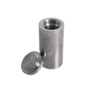
- Coordinated Metal & Plastic Supply: Combine stamped shields with CNC-machined housings, turned spacers, cast parts or molded components in one project. Define the supply scope and shared interfaces before release.
- Packaging for Your Assembly Line: Specify trays, layer packs or a reviewed tape-and-reel format. Orientation, pocket clearance and pickup area are checked for the selected handling method; automated placement is not assumed for every cover.
Technical FAQ (Frequently Asked Questions)
Other Products
Custom Modular Plastic Enclosures
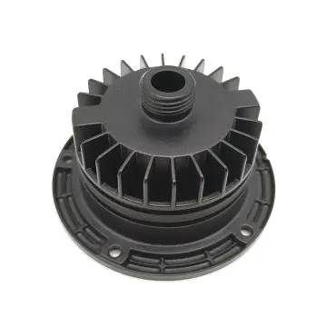
Custom Die Cast Aluminum Finned Housings
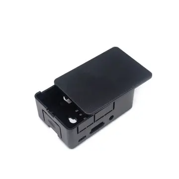
Custom Injection Molded Electronics Enclosure
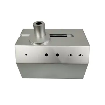
Custom Precision Sheet Metal Equipment Enclosure
Get a Fast, Technical Quote & Free DFM Review
Don't let tolerance stack-up delay your product launch. Submit your project details, and our engineering team will evaluate your design for manufacturability before the first cut.