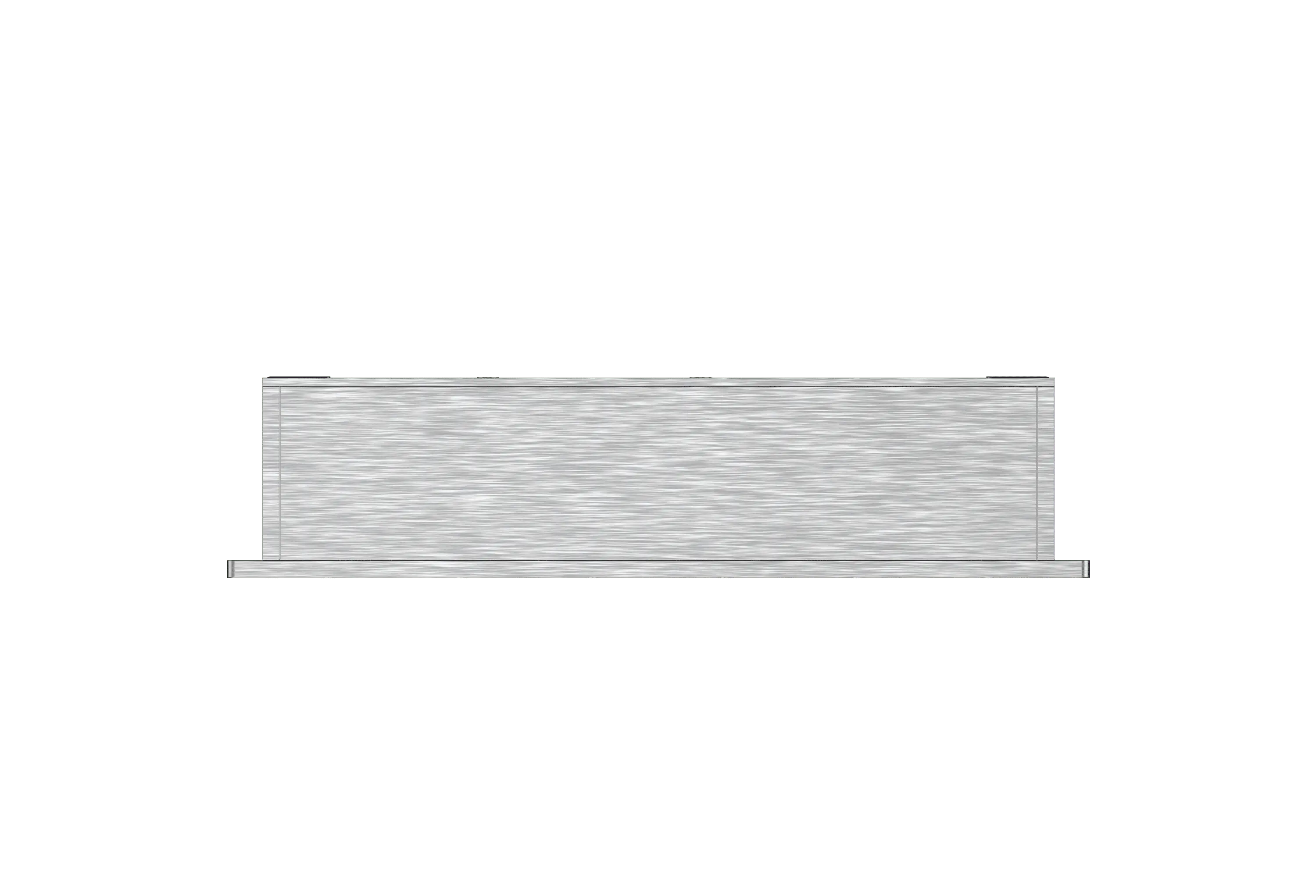
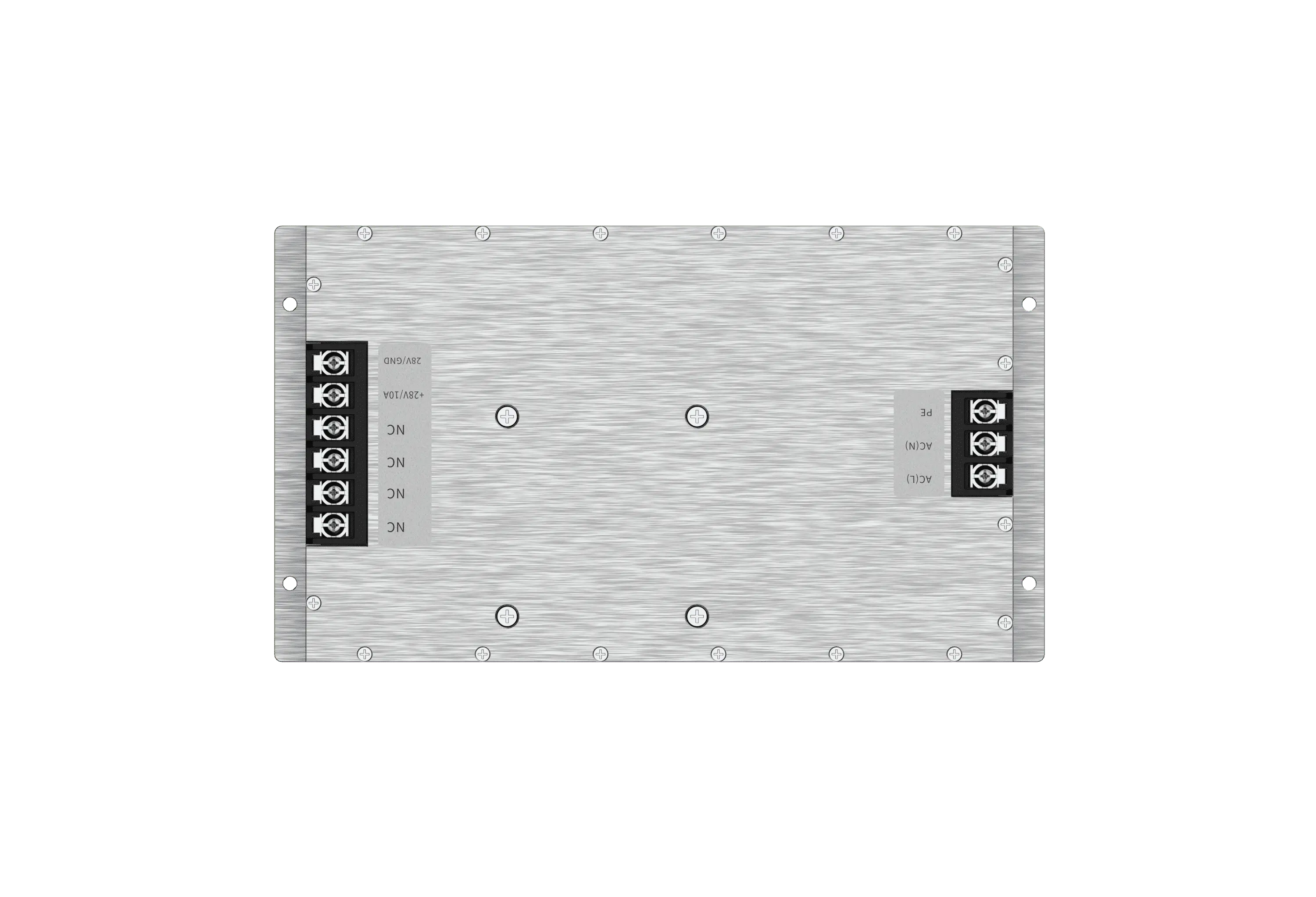
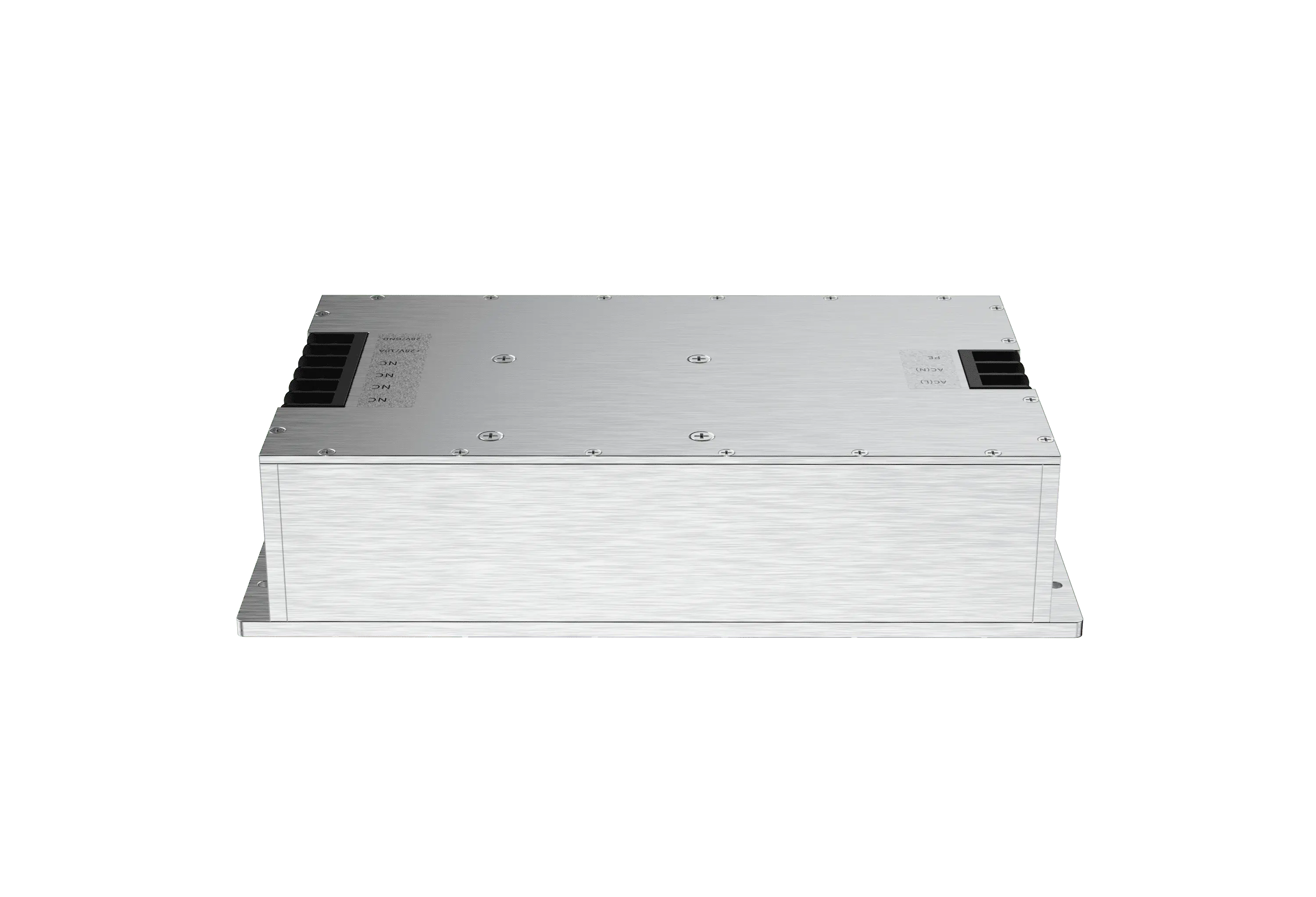
China Custom Aluminum Power Supply Enclosures Supplier, Products
Product Description
Product Overview
Manufacturing & Process Insights
Tooling & Manufacturing Route
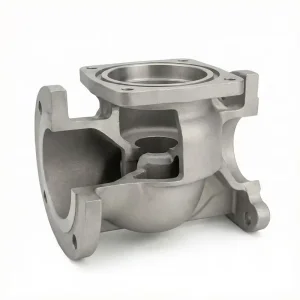
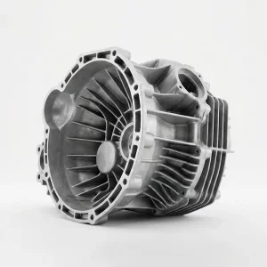
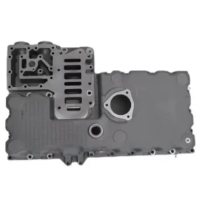
For designs suited to high-pressure die casting, we review the alloy, wall sections, draft, parting lines, gating and machining allowance before tooling. Venting or vacuum assistance is assessed for the casting. Machined or extrusion-based bodies remain options for suitable designs and quantities. Confirm body and cover construction during drawing review so prototype and tooling costs reflect the same production plan.
Secondary Precision CNC Machining
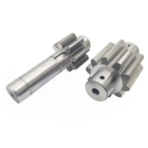
Machine mounting faces, PCB supports, terminal openings, cable-clearance features and threads to the approved drawing. Define datum references, finished dimensions, thread engagement and any gasket groove before production. A baseplate flatness target below 0.05 mm can be submitted for review against its surface span, material, finishing sequence and inspection method.
Thermal Interface Preparation
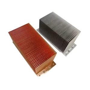
Define the component-to-baseplate contact areas, external mounting surface and space for thermal interface materials. Share actual heat dissipation, ambient conditions and installation details when setting requirements. Power-supply output wattage is not the heat load; fanless operation and temperature rise require validation with the complete electronics and mounting arrangement.
Surface Finishing & Contact Areas
Brushing, bead blasting, chemical conversion coating, powder coating and anodizing are evaluated against the selected alloy and service environment. Mark grounding, bonding and thermal-contact areas separately from cosmetic faces. Agree coating coverage, thickness and appearance requirements; anodizing is not a universal finish for every casting alloy.
Technical Specifications
| Parameter / Attribute | Specification / Project Options |
|---|---|
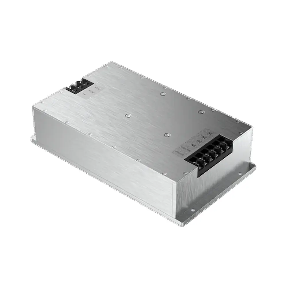
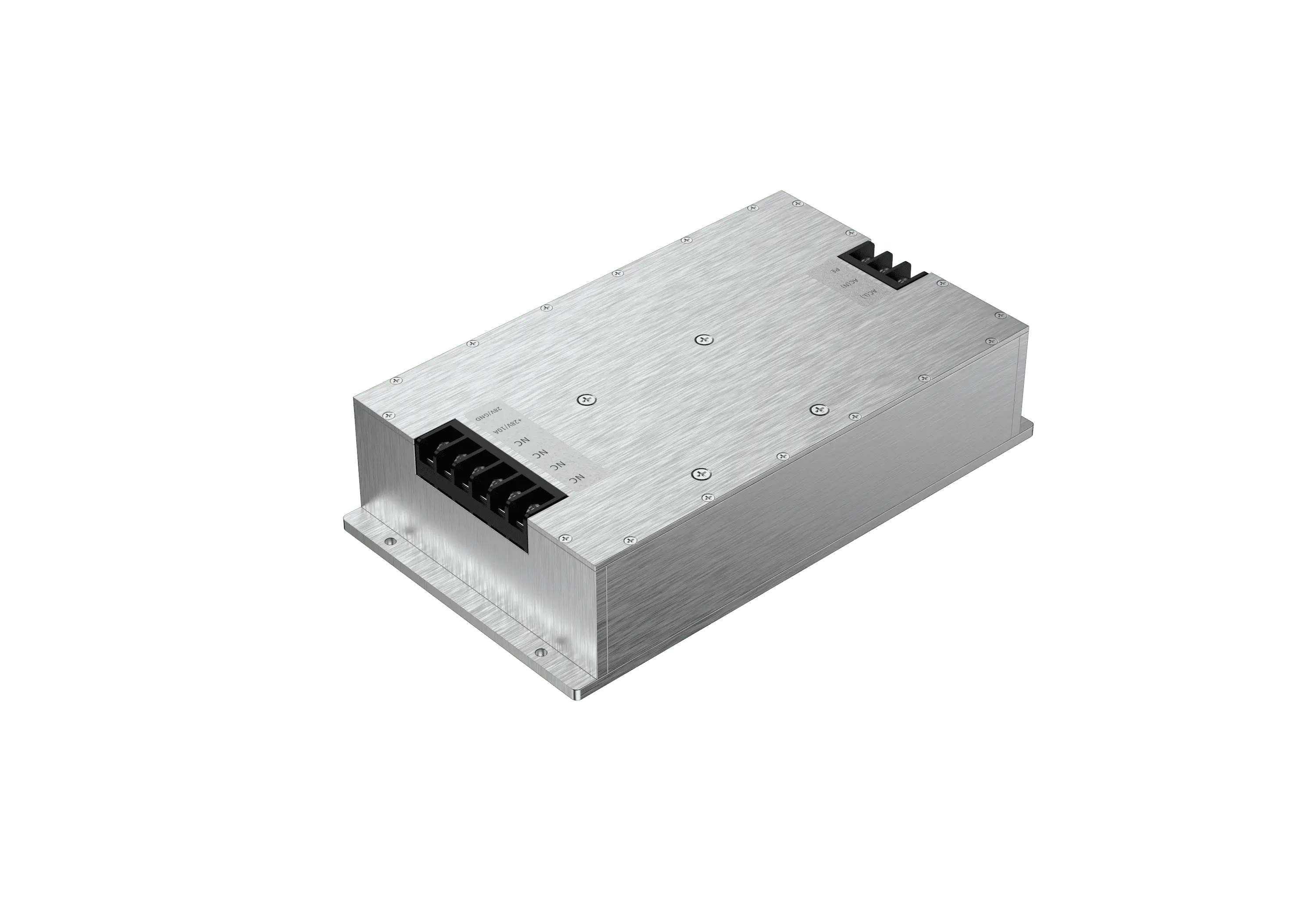
| Target Application | Industrial SMPS, motor drives, inverters and charging controls. 220V AC / 28V 10A is an application example, not a supplied electrical rating. |
| Manufacturing Route | Die casting plus CNC for suitable designs; machined or extrusion-based alternatives by review. Body and cover construction confirmed before quotation. |
| Alloy Options | Casting options: ADC12, A380, AlSi10Mg, AlSi9Cu3. Wrought / extruded options: 6061, 6063. Grade, condition and process compatibility confirmed per project. |
| External Dimensions | Length, width, height and flanges per drawing. Reference size: 215 x 115 x 50 mm only; not a fixed stock specification. |
| Internal Clearance | PCB outline, component heights, supports, terminal access and electrical clearances per assembly design; not determined by output wattage. |
| Baseplate Flatness | Review target: below 0.05 mm. Define the surface span, datum, finishing stage and measurement method. |
| Dimensional Tolerances | Critical-feature target: ±0.015 mm, subject to review. General and geometric tolerances per drawing. |
| Terminal Interface | Cutouts, recesses and fastener positions per terminal drawing. Pole count and labels per customer electrical design; terminal blocks quoted separately. |
| Mounting Configuration | Custom flanges, round holes or slots, hole spacing and installation clearances. Load path and tool access confirmed with the assembly. |
| Cover & Fasteners | Cover, screw pattern, thread engagement and gasket layout per drawing. Hardware itemized as required. |
| Ingress & Environment | No default IP rating. Target applies to the tested assembly, including lid, terminal openings, cable entries and seals. |
| Grounding & Insulation | Grounding points, contact areas and coating masks per electrical design. Insulation and dielectric checks covered by the assembly test plan. |
| Surface Treatment | Brushing or blasting where suitable; conversion coating, powder coating or alloy-compatible anodizing. Finish, coverage and appearance agreed. |
| Documentation & Compliance | Agreed material and inspection records. UL 94 applies to relevant plastic parts; finished-equipment approvals remain separate. |
Key Features & Sunmy Manufacturing Advantages
Custom Fit for Your Assembly
Specify the board envelope, wall sections, internal support positions, terminal layout and installation space. We review tooling access and shared interfaces before production, so a catalog enclosure does not dictate your design.
One Coordinated Mechanical Package
Request the body, cover, machined mounting faces, stamped brackets, inserts and specified seals in one quotation. Related terminal hardware or mechanical sub-assembly can be reviewed separately. The quotation identifies what is included without implying supply of a tested electrical power unit.
Thermal & EMC Interfaces Defined Together
Coordinate heat-transfer faces, lid joints and grounding contact areas in the same drawing review. Material and dimensional inspection support component acceptance; cooling performance, shielding effectiveness and electrical safety are verified against the assembled product requirements.
Prototype to Repeat Production
Evaluate samples before committing to production tooling. Sample quantity, tooling cost, inspection scope and batch schedule are quoted for the project. Send your 2D/3D drawings or sample details, material, finish and quantities for a manufacturing review and quotation.
Other Products
Custom Modular Plastic Enclosures...
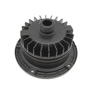
Custom Die Cast Aluminum Finned H...
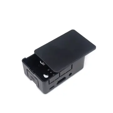
Custom Injection Molded Electroni...
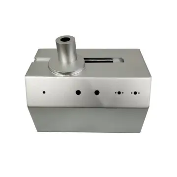
Custom Precision Sheet Metal Equi...
Technical FAQ for Engineering & Sourcing Buyers
Q1: Can prototypes support thermal, ingress and insulation checks before tooling?
A: Yes. We can prepare mechanical prototypes to the agreed design for assembly and bench evaluation. Specify the thermal, IP, insulation or vibration checks, test configuration and responsible party at RFQ stage. A successful machined prototype does not automatically qualify a later die-cast version; confirm which checks must be repeated on production-intent parts.
Q2: What quantities and lead times can Sunmy support?
A: Prototype, pilot and repeat-production quantities are reviewed individually. Please provide the trial quantity, expected repeat volume and required delivery date. Sample manufacture, die tooling, trial approval and batch production have separate schedules; we confirm the MOQ and lead time after reviewing geometry, alloy and finish, rather than impose one batch size on every project.
Q3: How are casting integrity and mounting-face flatness controlled?
A: For a confirmed die-cast design, define permitted casting discontinuities and required inspection before tooling. Review gating, venting and process settings, then machine critical faces as specified. Agree dimensional inspection, sampling and additional tests in the quality plan. Thermal-interface performance is checked under the agreed assembly test conditions, not inferred from a flatness result alone.
Q4: How do you handle thermal interface and heat dissipation requirements?
A: Component-to-baseplate contact areas, external mounting surfaces, and space for thermal interface materials are defined during technical evaluation. Actual heat dissipation and ambient installation details should be shared during RFQ to ensure proper fanless or active cooling validation.
Q5: Are surface finishes like anodizing suitable for all aluminum casting alloys?
A: Anodizing is not a universal finish for every casting alloy due to varying silicon and copper contents. We evaluate brushing, bead blasting, chemical conversion coating, powder coating, and alloy-compatible anodizing to match your service environment and material selection.
Q6: Are internal electronic components or terminal blocks included in the manufacturing scope?
A: No, our service covers custom mechanical enclosure manufacturing. Electronics are outside this scope. Terminal blocks, seals, gaskets, and mounting hardware are included only when specifically itemized in the project quotation.
Get a Fast, Technical Quote & Free DFM Review
Don't let tolerance stack-up delay your product launch. Submit your project details, and our engineering team will evaluate your design for manufacturability before the first cut.