OEM Custom Open Snap Bushings (Split-Type Cable & Panel Protection) Supplier, Exporter
Product Description
Product Overview & Application Focus
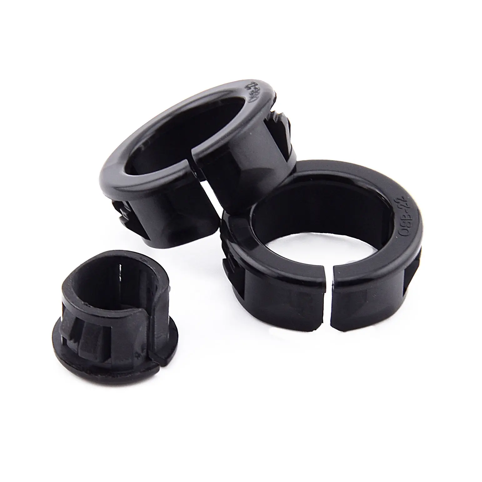
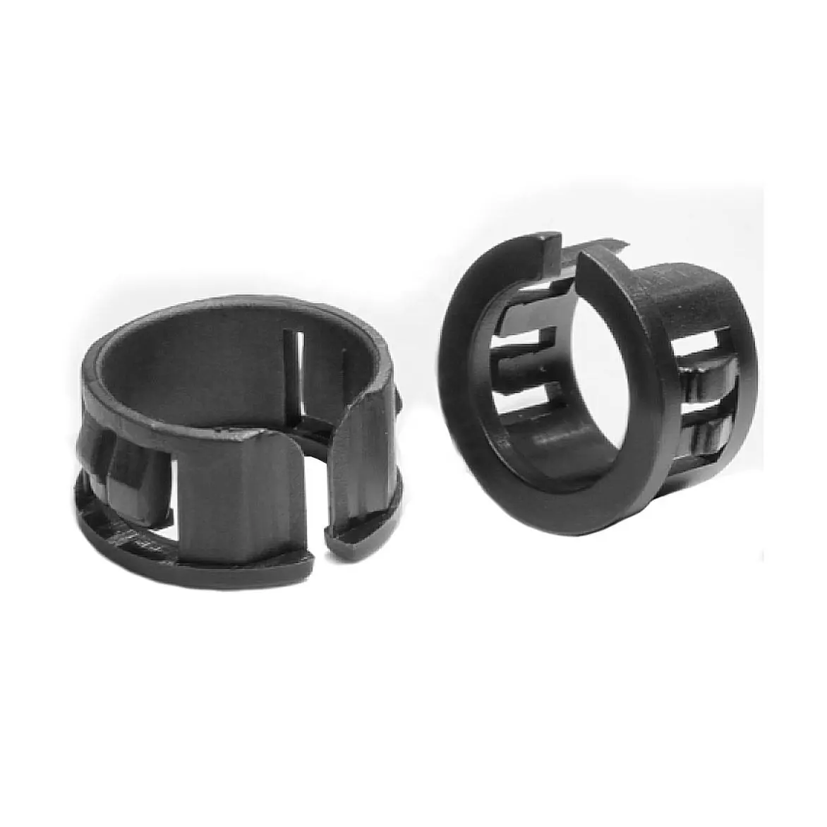
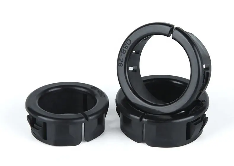
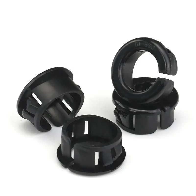
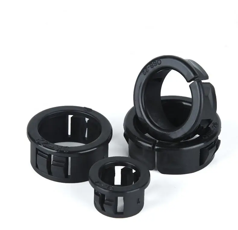
Fit the bushing to your panel, not your panel to a catalog size. Shenzhen Sunmy Hardware Co., Ltd. manufactures custom open snap bushings for power supplies, instruments, control cabinets, and cable assemblies. The split body fits around a cable without passing its connector through the bushing. Send your drawing or sample to customize the opening, flange, locking fingers, and material.
A rounded pass-through separates cable jackets from panel edges; molded locking fingers retain the bushing in the panel. This open component is not a cable clamp or waterproof gland. Bushing retention and cable strain relief are separate requirements.
Manufacturing & Tooling Insights (Injection Molding)
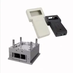
Process Execution: Sunmy coordinates drawing review, custom mold development, injection molding, and sample approval. We review panel fit, split opening, latch deflection, and wire-contact surfaces before tooling, with acceptance criteria agreed upon for the project.
-
Tooling & Cavity OptimizationMold steel, cavity count, and runner layout are selected for the geometry and order volume. Gates, vents, and parting lines are planned around flexible locking tabs and cable-contact surfaces.
-
Retention Finger Design & ValidationRoot radii, finger length, and locking steps are tailored to the specified panel. Insertion force, panel retention, and repeat-installation criteria are agreed upon for sample approval.
-
Engineering Resin SelectionPA66, PA6, PBT, or PC grades are evaluated against flexibility, temperature, and environment. Filled, flame-retardant, or UV-stabilized grades require review for snap geometry.
-
Degating & Surface ControlGate vestiges, flash, and cable-contact edges are controlled to the approved drawing and sample. Panel cutouts must still meet the specified edge condition.
Key Engineering Specifications
Made to order from your drawing or approved sample. Dimensions, resin, color, panel fit, and inspection requirements are defined by project; the options below are customizable.
| Parameter | Project Specification | Custom / OEM Options |
|---|---|---|
| Product Category | Open snap bushing for panel pass-through protection | Split geometry, flange profile and identification to print |
| Manufacturing Process | Custom tooling and plastic injection molding | Prototype, pilot and repeat production; cavity count by project |
| Cable / Harness Interface | Round cables, wire bundles or flat ribbon cables | Passage shape and clearance matched to the actual harness |
| Clear Opening (Bushing I.D.) | Finished passage size, distinct from panel-hole and flange diameters | Round, oval or rectangular opening to specified bundle envelope |
| Panel Cutout & Envelope | Panel-hole tolerance, flange diameter and overall height to drawing | Round or shaped cutouts, anti-rotation details, low-profile bodies |
| Panel Thickness / Grip Range | Finished panel thickness and tolerance, including coating | Single or stepped locking fingers for approved grip range |
| Resin / Material Grade | PA66 as a starting option; exact grade agreed before tooling | PA6, PBT, PC or modified grades after material review |
| Flammability Rating | Rating tied to selected grade, color and applicable thickness | V-0 / V-2 targets; supporting records and testing agreed |
| Service Temperature | Continuous and peak conditions reviewed by grade and assembly duty | Thermal, UV and chemical exposure requirements defined in RFQ |
| Color & Surface Finish | Black, natural or specified color; texture to approved sample | RAL / Pantone matching and molded identification features |
| Panel Locking & Retention | Molded fingers retain bushing in panel, not the cable | Insertion, panel pull-out and cycling criteria agreed by project |
| Sealing & Cable Anchorage | Open pass-through; no waterproof seal or clamp rating claimed | Separate sealing or clamping design where assembly requires it |
Key Engineering Features & OEM Capabilities
-
Side-Entry InstallationFit the split body around the cable instead of passing its connector through the bore. Check access, panel-hole clearance, and installation sequence with the actual harness.
-
Panel Fit Without FastenersMolded locking fingers locate the bushing in the approved cutout. Match the grip range to finished panel thickness, including coating, and verify retention on samples.
-
Rounded Wire-Contact SurfacesThe entry rim separates the cable jacket from the panel edge. Specify cable movement and wear requirements where the harness flexes in service.
-
Full OEM CustomizationCustomize passage, flange, body depth, split, and locking tabs without catalog limits. Sunmy supports sample development through repeat production.
Other Related Products
Custom Modular Plastic Enclosures
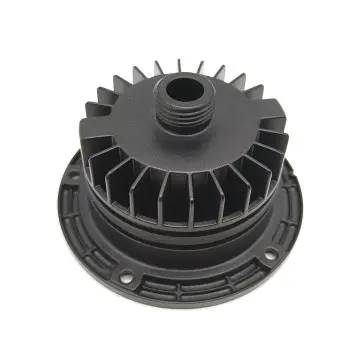
Custom Die Cast Aluminum Finned Housings
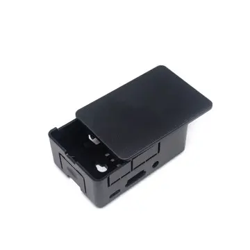
Custom Injection Molded Electronics Enclosure
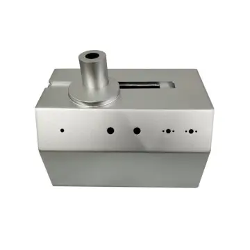
Custom Precision Sheet Metal Enclosure
Technical FAQ for OEM Procurement & Engineering Teams
A: Yes. Send the panel cutout and tolerance, finished panel thickness, cable-bundle dimensions, and installation sequence. Include 2D/3D drawings or a sample where available. We review the opening, grip range, and tooling route around your assembly requirements.
A: Yes. Specify the resin grade or flammability target and color. Supporting material recognition must cover the selected grade, color, and thickness. Required declarations and testing requirements are agreed upon with the project order.
A: No. It protects the pass-through edge and retains itself in the panel; it does not clamp the cable or seal the opening. Where anchorage or ingress protection is required, specify a separate clamp, gland, or validated sealing design.
A: Prototype quantities, mold cavities, T1 timing, and production lead time are quoted after drawing and material review. No universal MOQ or delivery time applies. Send your project details for a specific quotation.
A: We accept standard 3D CAD formats including STEP, IGES, and X_T, as well as 2D vector drawings (DWG, DXF, PDF) for critical dimension tolerances and surface finish specs.
A: During DFM, we evaluate your maximum and minimum panel thickness tolerances (including powder coating/plating). The locking finger ramp and step geometry are specifically designed and tested during T1 sample approval to ensure tight engagement without tab fracture.
Get a Fast, Technical Quote & Free DFM Review
Don't let tolerance stack-up delay your product launch. Submit your project details, and our engineering team will evaluate your design for manufacturability before the first cut.