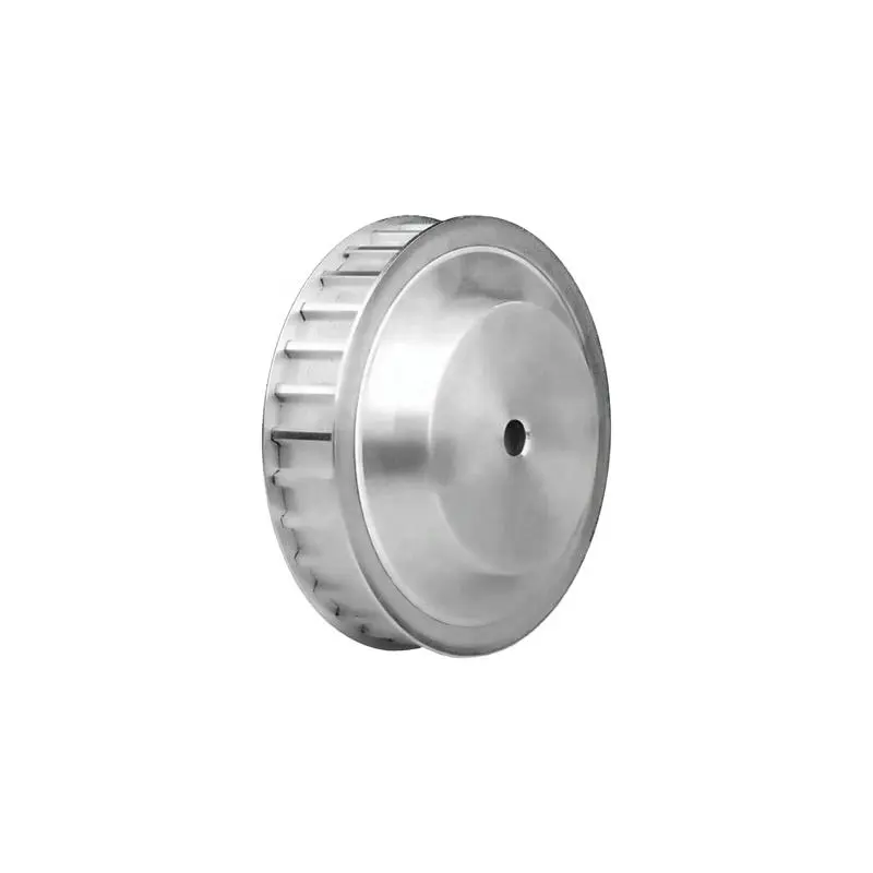
OEM Custom CNC Machined HTD 3M Aluminum Timing Belt Pulley Suppliers, Service

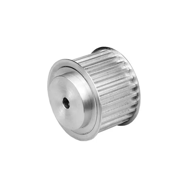
Shenzhen Sunmy Hardware Co., Ltd. manufactures custom aluminum timing pulleys from customer drawings, CAD models or approved samples. HTD 3M-15 identifies the reference configuration: 3.00 mm pitch for a nominal 15 mm HTD 3M belt. Tooth count, face width, bore, hub, flanges, material and finish can all be customized. Confirm the exact mating belt profile before production; matching pitch alone is insufficient.

Product Description

Product Overview & Engineering Scope

Shenzhen Sunmy Hardware Co., Ltd. manufactures custom aluminum timing pulleys from customer drawings, CAD models or approved samples. HTD 3M-15 identifies the reference configuration: 3.00 mm pitch for a nominal 15 mm HTD 3M belt. Tooth count, face width, bore, hub, flanges, material and finish can all be customized. Confirm the exact mating belt profile before production; matching pitch alone is insufficient.

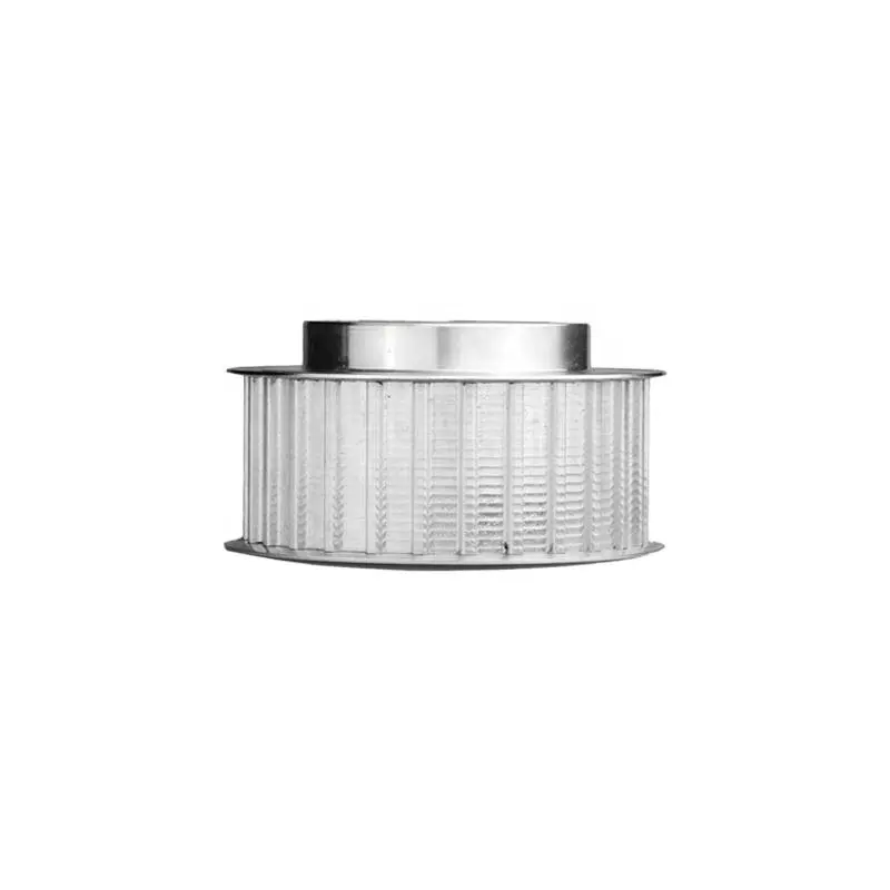
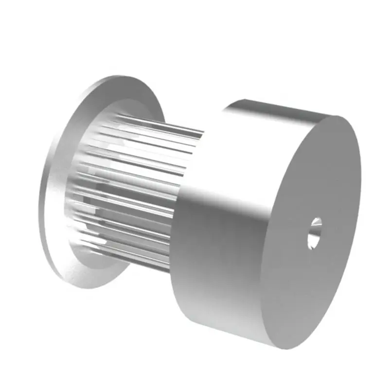
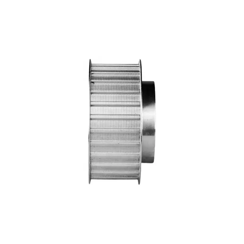
Material options include 6061-T6 and 7075-T6 aluminum, with grade and temper specified per order. Reference sizes are neither catalog limits nor a stock guarantee. Pilot bores, finished bores, keys, D-bores, set-screw holes and split-clamp hubs can be evaluated. Photographs show example configurations; the approved drawing defines the supplied geometry and finish.

Application Areas

Custom components evaluated against exact equipment requirements:

Factory Automation & Robotics Belt-driven positioning stages, linear actuators and pick-and-place modules.
Precision CNC Machinery Laser cutters, engravers, CNC router axes and 3D-printer motion stages.
Packaging & Material Handling Conveyors, form-fill-seal equipment, indexing and sorting mechanisms.
Food, Beverage & Pharma Equipment Drive components with customer-specified cleaning, material and finish requirements.
Electronic Assembly & Testing Optical inspection stages, handling modules and test-equipment drives.
Process & Manufacturing Insights

The following steps describe available manufacturing and inspection operations. Sunmy coordinates the selected route, process sequence and quality requirements for the approved design and production quantity.

1
Material Selection & Blank Preparation
Confirm alloy, temper, stock form and required material records. Select roughing allowances and any stress-management steps to suit the blank and preserve the specified final material condition. Additional testing is included when required by the material or project specification.
2
Datum-Controlled CNC Turning
Machine the tooth blank, hub, flange seats and bore from coordinated datums. Use a common setup where practical and transfer the functional bore axis consistently to later operations. Inspection references the final drawing datums and specified radial/axial runout limits.
3
Matched-Profile Tooth Cutting
Select CNC hobbing or suitable profile cutting for the required tooth geometry and quantity. Match tooling and inspection references to the mating belt; confirm any specified standard and edition. Different belt systems are not assumed interchangeable solely because their pitch matches.
4
Flange Manufacture & Attachment
Flange material, diameter, thickness and number follow the drawing. Separate flanges may be staked or swaged; integral flanges require suitable machining access. The attachment sequence, retention criteria and testing are defined for the specified flange construction and operating conditions.
5
Finished Bores, Keyways & Fastening Features
Bore or ream to the required shaft fit. H7 numerical limits depend on nominal bore size, and the resulting fit also depends on the mating shaft. Keyway geometry, set-screw threads and angular positions are defined individually; clamping designs require sufficient hub material.
6
Deburring & Surface Finishing
Control tooth-edge burrs, bore entries and flange contact edges. Options include clean as-machined surfaces, clear or black anodizing, hard anodizing and selected plating. Specify treatment, coating thickness and masking where needed, with final dimensions checked after finishing as required.
7
Inspection & Quality Documentation
Select suitable profile inspection, bore gauges, runout fixtures and coordinate measurement for the critical features. Agree sampling, first-article reporting and material or finish records before production. Balance testing and application trials are separate requirements, not automatic equivalents of dimensional inspection.
Technical Specifications & Customization Matrix

Reference configurations and custom options are shown below. The approved drawing and quotation define the final dimensions, materials, operating requirements and acceptance criteria. Listed sizes do not limit customization.

Parameter / Attribute Reference Configuration Sunmy Custom Capability (OEM/ODM)
Product Series HTD 3M-15 reference configuration Fully custom pulleys to drawings or approved sample specifications
Tooth Profile HTD 3M curvilinear; confirm mating belt Other profiles to the matching belt drawing; no pitch-only interchangeability
Pitch 3.00 mm (0.118 in) Other pitches and tooth systems reviewed to the specified belt
Compatible Belt Width 15 mm nominal belt width Other belt widths with matched tooth face width and flange clearance
Face Width & Axial Envelope Usable tooth width specified separately Define flange spacing, flange thickness and overall hub-to-face length
Tooth Count (Z) 10T–72T reference options Other counts subject to belt, hub geometry and tooling review
Tooth Outside Diameter (OD) Defined by tooth count and profile geometry Specify tooth OD separately from pitch diameter and flange OD
Pitch Diameter (PD) PD = Z × p / π; p = belt pitch At 3 mm pitch: 10T ≈ 9.55 mm; 72T ≈ 68.75 mm
Bore Supply Condition Unbored blank, pilot bore or finished bore State required delivery condition; stock blanks are not assumed
Finished Bore Options Size and geometry to the shaft drawing Round, stepped, keyed, D-bore, spline or clamp interface
Bore Fit Tolerance H7 or explicit dimensional limits as specified Numerical limits depend on nominal size; review the mating shaft fit
Shaft Locking Methods Selected to shaft and load requirements Set-screw holes, keyways or split-clamp hubs; hardware scope agreed
Hub Configuration Stepped or single-sided hub by design Custom height/diameter, double or flush hubs and relief pockets
Flange Construction Flanged or unflanged per drawing Custom flange material, diameter, number and attachment method
Primary Material Aluminum 6061-T6 / 7075-T6 options Steel, stainless steel, brass or POM alternatives reviewed on request
Surface Treatment As-machined or customer-selected finish Clear/black/hard anodizing or suitable plating; final-fit allowance defined
Runout & Tooth Finish Limits and datums defined on the drawing Agree radial/axial runout, measurement surfaces and roughness requirements
Balance & Operating Speed Operating speed and duty defined per project Specify service speed, balance criteria, test setup and validation scope
Drawing Formats 2D: PDF, DWG, DXF; 3D: STEP, IGES Sample-based development with drawing approval before production
Quality Documentation Defined in the order and inspection plan Dimensional, material, finish and conformance records as agreed
Key Features & Engineering Advantages
Belt-Matched Synchronous Engagement The tooth system and width are matched to the selected belt instead of inferred from pitch alone. Performance requirements are tied to the assembled drive, with compatible belt selection, load, speed, tension and alignment considered during approval.
Weight-Conscious Material & Hub Design Aluminum grade, hub dimensions and weight-relief features can be selected together to meet the required assembly envelope. Compare alternative constructions against the specified loads, shaft connection and finish before approving the production design.
Coordinated Bore-to-Tooth Accuracy Control the bore, tooth geometry and locating faces through a defined datum and inspection plan. Concentrate precision on functional interfaces rather than assigning the same extreme tolerance to every feature.
Application-Specific Flange Options Choose single, double or unflanged construction to suit the belt-drive layout. Specify retention requirements and installed clearances; flanges are not a substitute for correct shaft alignment or belt tension.
Multi-Process Manufacturing Coordination Sunmy combines custom machining and turning with coordinated stamping, casting, injection molding and finishing for related components. The quotation defines supply scope, inspection responsibilities and the route from prototype approval to repeat production.
Technical FAQ for International Procurement
Q1: Can Sunmy customize the pulley beyond the reference sizes and bore options?
A: Yes. Tooth count, belt width, bore, keyway, set-screw arrangement, hub geometry, flange construction, material and finish can be manufactured to your requirements. Send the shaft and belt details with drawings or a sample. We review compatibility and manufacturability, then confirm the production drawing before work begins.
Q2: How are prototype and production lead times confirmed?
A: We quote prototypes, dedicated cutting tools, finishing and repeat production separately where relevant. Timing depends on the approved geometry, material availability, tooling, inspection scope and quantity. Provide your target date and trial quantity so we can confirm a realistic schedule and any practical expedited option.
Q3: What information is needed for DFM review and quotation?
A: Send a STEP or IGES model with a dimensioned PDF, DWG or DXF drawing. Include the exact belt profile, pitch, tooth count, belt width, shaft interface, material, finish and quantities. Relevant speed, torque and installation details help define the review. Sample-based development is also supported, with drawings submitted for approval.
Q4: How are tooth accuracy and repeat-order consistency checked?
A: The inspection plan references the approved belt profile and drawing revision. Suitable methods are chosen for tooth geometry, bore fit, radial/axial runout, flange position and surface condition. Sampling and report scope are agreed before production. First-article, material, finish and conformity records are supplied as specified; balance testing is agreed separately.
Q5: Do you support small trial batches and ongoing OEM supply?
A: Yes. Prototype, pilot and repeat-production quantities can be evaluated without forcing a standard catalog size. Minimum practical quantities and price breaks depend on the design, material, tooling and finishing route. Send your drawing or sample details, initial quantity and expected repeat volumes for a project-specific offer.
Other Products
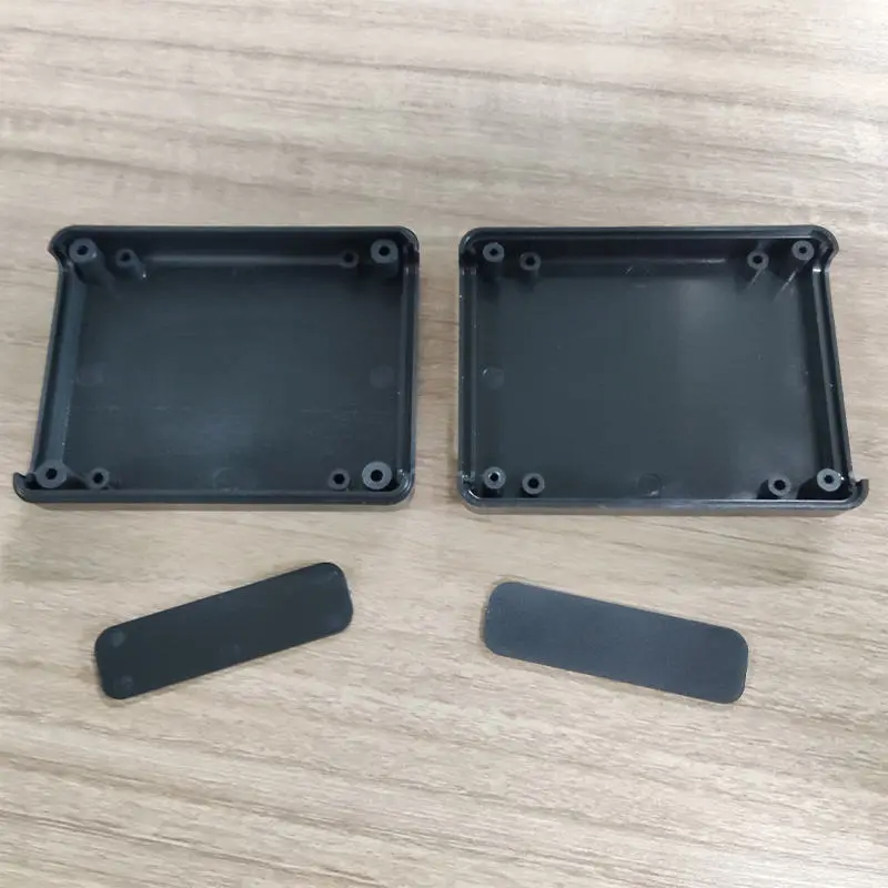
Custom Modular Plastic Enclosures | Removable End Panels for OEM Electronics
Custom Modular Plastic Enclosures...
Custom Die Cast Aluminum Finned Housings & End Caps
Custom Die Cast Aluminum Finned H...
Custom Injection Molded Electronics Enclosure | OEM Project Box
Custom Injection Molded Electroni...
Custom Precision Sheet Metal Equipment Enclosure
Custom Precision Sheet Metal Equi...
Get a Fast, Technical Quote & Free DFM Review

Don't let tolerance stack-up delay your product launch. Submit your project details, and our engineering team will evaluate your design for manufacturability before the first cut.
Related Products