High-Quality Precision CNC Turned Stainless Steel Stepped Shaft - Custom Solutions from China Suppliers and Factory Manufacturers, Quotes
Product Description
Product Overview
Manufacturing Process & Technical Insights
Coordinated CNC Turning & Milling
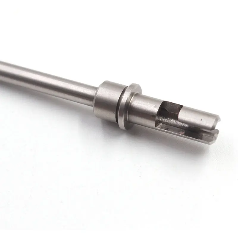
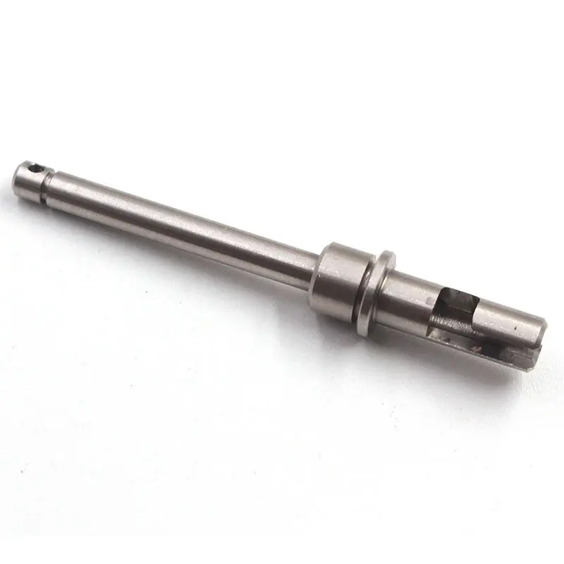
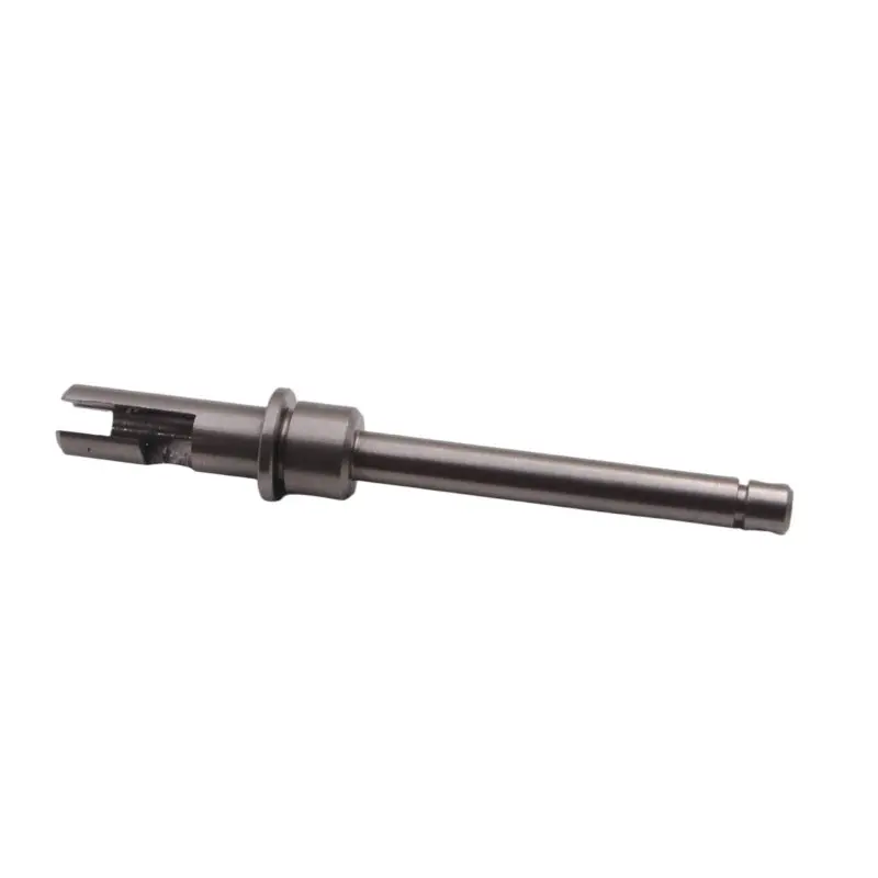
Shaft profiles, collars and grooves are turned, while cross-holes, axial bores and slotted or clevis ends are machined to the drawing. Turn-mill machining or separate fixtured operations are selected according to geometry and batch size. The process plan identifies workholding, locating datums and inspection points for the critical shaft and end features.
Functional Feature Review
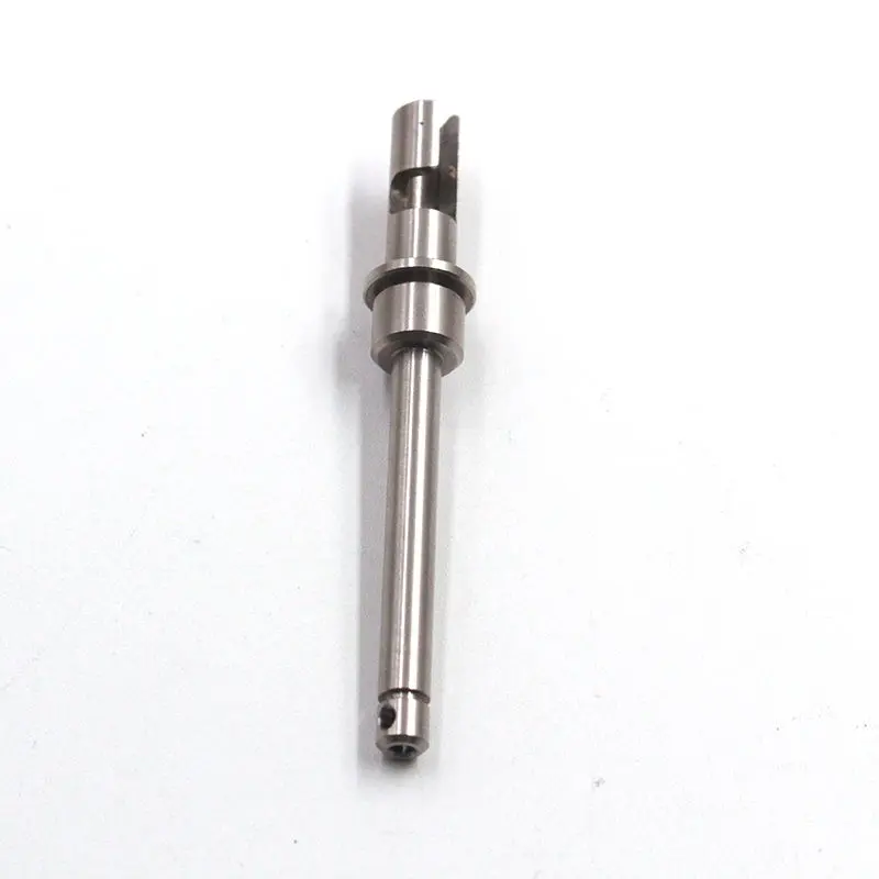
Shaft diameters, shoulder positions, groove width, slot dimensions and hole locations are checked against the intended mating components. Retaining-ring details, pin fits and internal-thread callouts must be specified on the drawing. The slotted and forked end designs shown are alternative configurations, not interchangeable standard interfaces.
Deburring, Cleaning & Surface Finish
Machined edges, cross-hole exits and slot intersections are reviewed for burr control. Cleaning and any specified passivation or polishing are included in the agreed process plan. Finish requirements are defined for the selected stainless steel grade. Any requested corrosion testing needs an agreed test method, acceptance criteria and reporting scope before production.
Stress Relief & Heat Treatment (Optional)
Heat treatment is evaluated against the selected material grade, required condition and finished dimensions. Specify the target hardness, treatment specification and required records in the RFQ. The processing sequence and final dimensional checks are then defined in the manufacturing plan.
Key Technical Specifications
Specifications follow the approved drawing and quotation. The table lists customization options, not measured dimensions or verified performance ratings for the photographed parts:
| Parameter | Technical Description / Requirements | Customization Scope |
|---|---|---|
| Product Type | Precision turned stepped shaft with collar and machined end features | Slotted or clevis-style end variants per approved drawing |
| Primary Process | CNC turning, milling, drilling, grooving and tapping | Turn-mill or separate operations; grinding evaluated if specified |
| Material Grades | Stainless steel options for review: 303, 304, 316L, 17-4PH, 416, 420, 430 | Carbon steel, alloy steel, brass or titanium subject to project review |
| Machining Tolerances | Diameter fits, lengths and feature tolerances per approved drawing | Critical limits confirmed after material and geometry review |
| Geometric Tolerances | Shaft runout, shoulder-face and feature-location requirements per drawing | Datum system, measuring method and acceptance criteria agreed |
| Dimensional Capacity | Outer diameters, step lengths and overall length supplied in the RFQ | Feasibility and workholding assessed for the requested dimensions |
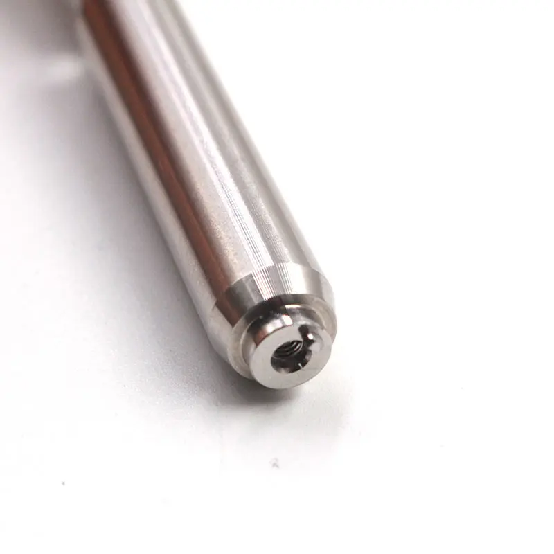
| Functional Features | Stepped diameters, collar, ring groove, cross-hole and machined end features | Clevis or slot end, tapped bore, flats, keyways or other specified features |
| Surface Roughness | Surface finish specified separately for journals, milled faces and other areas | Grinding or polishing evaluated for the drawing requirements |
| Surface Treatments | Deburring and cleaning; passivation or polishing when specified | Other finishes evaluated for grade compatibility and application |
| Quality Inspection | Dimensional and visual inspection to the agreed inspection plan | FAI and material records by agreement; PPAP scope requires confirmation |
| Drawing Formats | STEP, IGES, PDF, DWG and DXF; native CAD files by confirmation | Provide critical dimensions, datums, thread details and finish requirements |
| MOQ & Prototype | Prototype, pilot and repeat-production quantities quoted individually | Share first-order quantity, annual demand and sample requirements |
| Production Lead Time | Confirmed after drawing, material, quantity and finishing review | Prototype approval and repeat-order schedules agreed separately |
Key Features & Competitive Advantages
-
Coordinated Shaft and End Features: Turning, grooving, drilling and milling are reviewed as one manufacturing package. Shared drawing datums link the shaft diameters, shoulder faces and end features, helping the buyer define assembly requirements without separate, conflicting component specifications.
-
Material and Finish Matched to the Project: Specify the stainless steel grade, operating environment and required material condition. Passivation, heat treatment, coatings and any application-specific qualification records are then reviewed against the project requirements.
-
Assembly-Focused Surface Requirements: Separate finish and edge callouts for journals, grooves, holes and slot faces focus inspection on the surfaces that engage mating parts. Required surface quality and burr limits form part of the agreed acceptance criteria.
-
One Point of Manufacturing Coordination: Sunmy coordinates machining, specified finishing, inspection and packaging through one project contact. The quotation identifies the included operations and documentation for sample approval and repeat orders.
-
Prototype-to-Production Support: Sample quantities, pilot batches and repeat orders are quoted to match the project stage. Approved samples and controlled drawing revisions provide the reference for subsequent orders; delivery schedules and any stocking arrangements require separate agreement.
Technical FAQ for B2B International Buyers
Q1: How are shaft fits, runout and cross-hole locations controlled?
Q2: Can Sunmy Hardware produce custom shafts from drawings or physical samples?
Q3: Which quality reports and material documents can be included?
Q4: How are prototype and production lead times determined?
Q5: How are precision shafts protected during international transit?
Q6: What surface roughness and dimensional tolerance standards do you follow?
Other products
-
Custom Cast Stainless Steel Industrial Bridge Handle
-
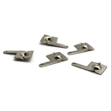
Custom Precision Stamped Battery Contact Plates & Terminals
-
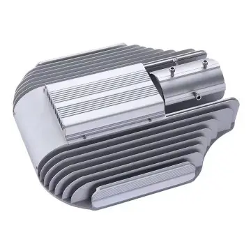
Custom Die-Cast Aluminum LED Luminaire Housing
-
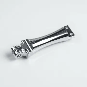
Custom CNC Machined Robot Finger Joint Link
Get a Fast, Technical Quote & Free DFM Review
Don't let tolerance stack-up delay your product launch. Submit your project details, and our engineering team will evaluate your design for manufacturability before the first cut.