1 / 5
High-Quality Custom CNC Machined Aluminum Enclosure for RF & Industrial Sensor Modules Product, Factories
Product Description
Product Overview & Target Industry Applications
Build the enclosure around your electronics, not the other way around. Shenzhen Sunmy Hardware Co., Ltd. manufactures CNC machined aluminum enclosures to your PCB layout, connector positions and assembly envelope. Pocket depths, mounting bosses, port openings and cover interfaces are made to your drawings or an approved sample-based design, from prototype through repeat production.
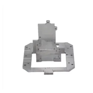
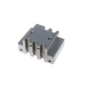
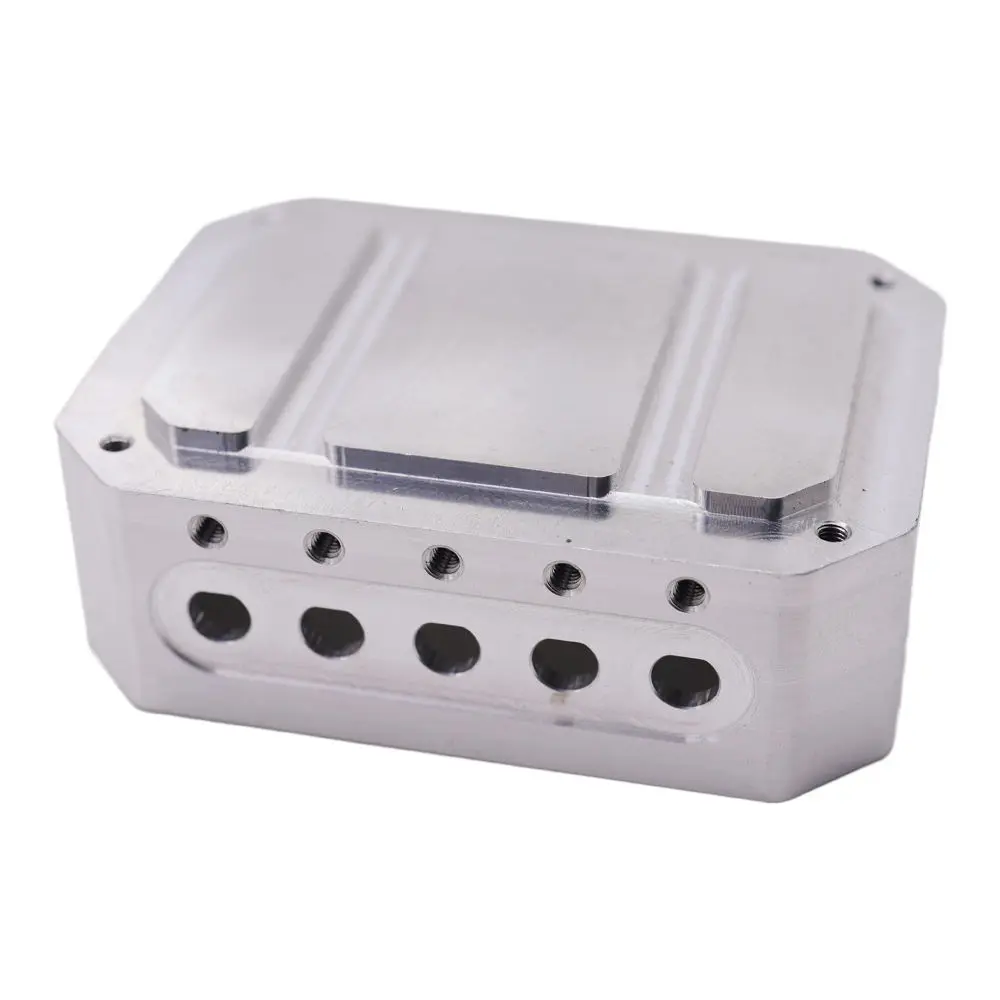
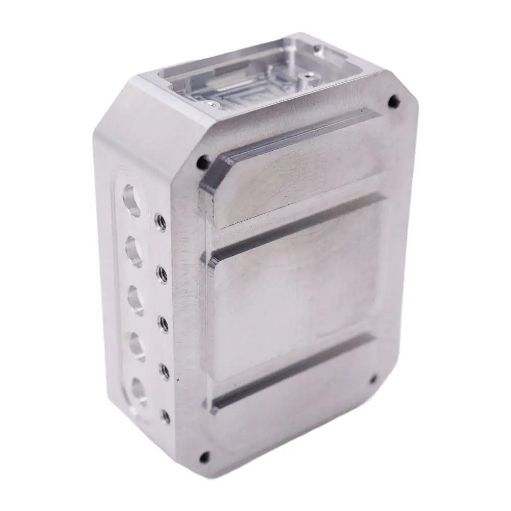
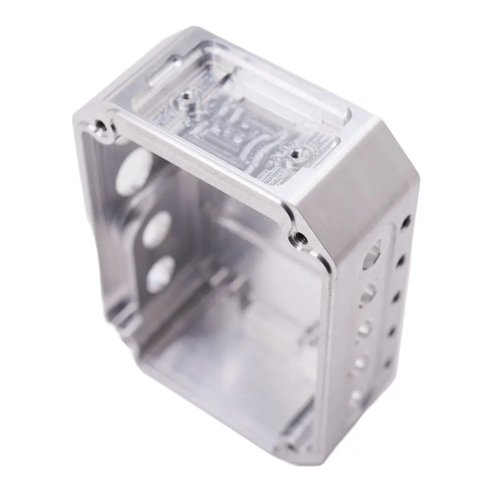
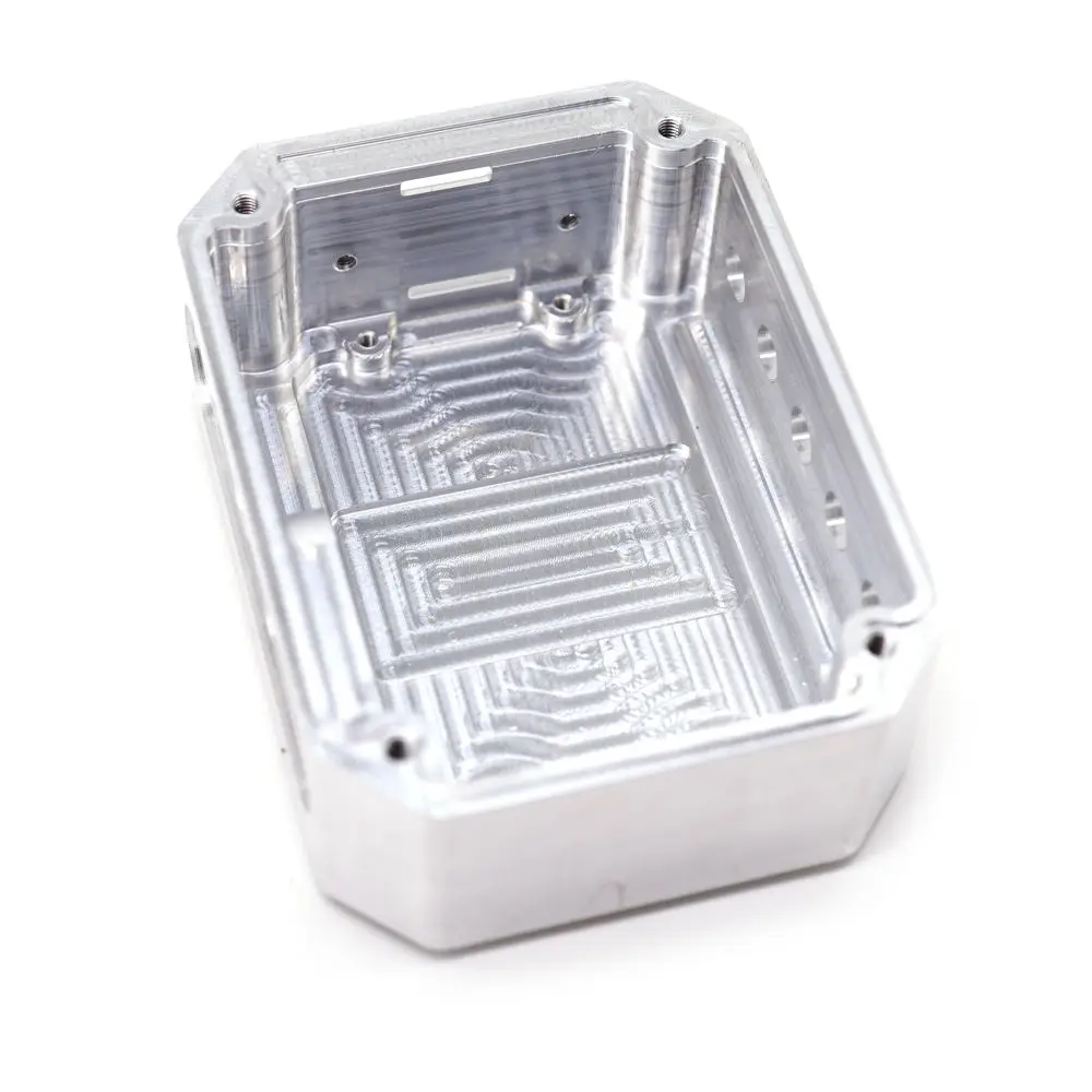
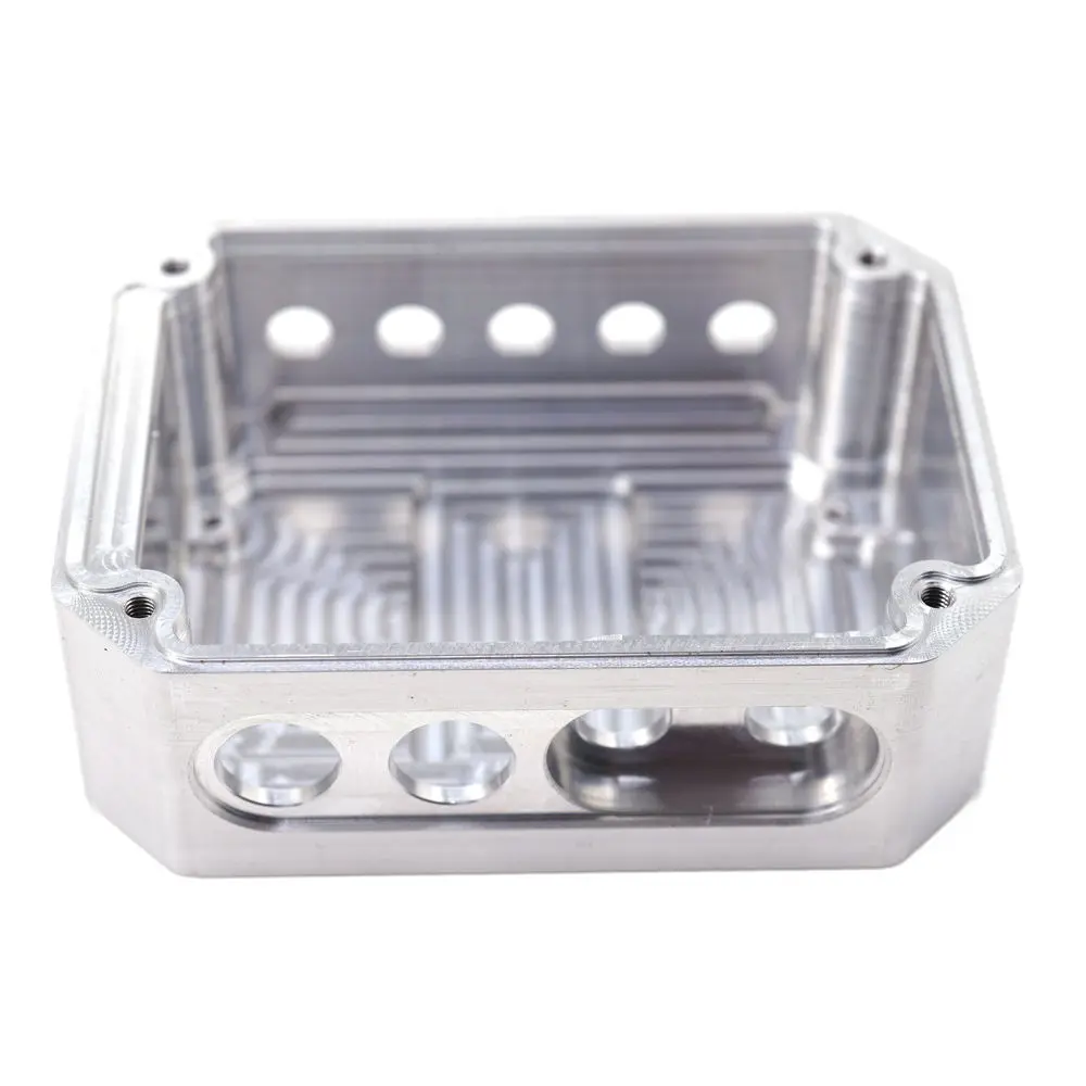
Applications & Supply Scope: RF communications, industrial sensors, edge devices and optical-networking hardware. The illustrated body shows pocketing, mounting features and multi-face openings. Specify whether you need body-only machining or a defined housing-and-cover package; gaskets, connectors and fasteners are included only when listed in the quotation.
Precision Manufacturing & Engineering Insights
2.1 Billet CNC Machining & Production Route
The pocketed body is machined from the specified wrought aluminum stock. CNC machining supports custom geometry and drawing revisions without a dedicated casting die. For repeat volumes, casting plus finish machining can be assessed as a separate route. Neither process alone establishes leak tightness, impact resistance or shielding performance.
2.2 Integrated Thermal Management Architecture
Internal bosses and exterior pads can be dimensioned as mechanical supports or thermal interfaces to your layout. Specify contact area, pad height, flatness, finish and thermal interface material where needed. Heat transfer depends on the contact conditions and complete thermal path; machined pads do not eliminate thermal resistance.
2.3 Multi-Axis Interface Ports & Precision Threading
Multi-Face Geometry: Tool access determines the fixtures and number of setups. Multi-axis machining is selected where useful, with port positions and mounting faces controlled from agreed datums.
- RF / coaxial ports: Bore sizes, recesses, spacing and retention-hole patterns to the selected connector drawing.
- Power / sensor feedthroughs: Circular or shaped openings, cable-gland ports and mounting recesses to print.
- Data / ribbon cutouts: Rectangular slots sized for the mating part and assembly clearance.
- Threaded mounts: PCB bosses and cover-fastening holes with specified thread size, engagement and blind-hole depth.
2.4 Perimeter Groove & Lid Interface
Machine the groove to the selected O-ring, molded seal or conductive-gasket specification, including width, depth, corner radii and finish. Confirm lid flatness, fastener spacing and compression requirements. Environmental sealing and EMI requirements are reviewed separately; one gasket does not automatically satisfy both.
Technical Specifications
All features are made to your drawings. Values below are RFQ reference targets, not fixed catalog sizes or verified test results. Final specifications and supply scope are agreed before production.
| Parameter / Attribute | Specification / Project Options |
|---|---|
| Product Classification | Custom CNC machined aluminum enclosure for RF and industrial sensor modules |
| Primary Material Options | 6061-T6, 7075-T6, 6063 or 5052, with alloy, temper and stock form specified for the project |
| Alternative Metals | Stainless steel 304 / 316L, brass, copper or titanium; material and machining route reviewed to print |
| Machining Technology | CNC milling, drilling, tapping and deburring; multi-axis machining and fixtures selected to suit feature access |
| Dimensional Tolerances | Drawing-specific. Example targets: ±0.05 mm, or ±0.01 mm on selected features, subject to review. ISO tolerance class is specified separately. |
| Sealing-Face Flatness | To the drawing and feature span; ≤0.05 mm may be specified for review, not assumed for every sealing face |
| Surface Roughness | Specify by surface: e.g. Ra 1.6–3.2 µm or Ra 0.8 µm on designated machined faces. Blasted texture to approved sample. |
| Surface Finishing Options |
• Cleaned as-machined or bead-blasted finish • Type II / Type III anodizing; color and thickness to spec • Chemical conversion coating, e.g. SurTec 650 if specified • Selective masking of gasket / grounding contacts • Electroless nickel or laser marking to project requirements |
| Enclosure Architecture | Pocketed one-piece body; internal bosses, steps and optional partitions to the approved design. Lid and accessories separately specified. |
| Port Cutouts & Interfaces | Round, recessed or rectangular openings to mating drawings. SMA / BNC / N-type, M12 and gland interfaces are customization options. |
| Thread Standards | Metric or UN-series threads to print, with size, pitch, class and engagement defined; thread inserts where specified |
| Thermal Interfaces | Internal component-support pads and exterior mounting faces to layout; contact conditions and thermal performance validated in the assembly |
| Sealing & EMI Requirements | Groove and contact surfaces matched to the lid and selected gasket. IP67 / IP68 or shielding targets require agreed assembly testing. |
| Custom Dimension Envelope | Reference only: L 30–600 × W 20–400 × H 10–200 mm. Submit other sizes for review; not a fixed catalog or stock range. |
| Quality Assurance & Testing | Drawing-based inspection plan, thread gauging and finish checks as agreed. Request FAI and EN 10204 3.1 material documentation at quotation. |
| Project Documentation | Material, finish and compliance requirements agreed at RFQ. Any required RoHS / REACH or management-system evidence must be confirmed for the order. |
| Supported CAD Formats | STEP / STP, IGES, Parasolid, SolidWorks, DXF / DWG and 2D PDF; native-file compatibility confirmed on receipt |
Core Features & Engineering Advantages
✔ PCB-First Customization
Match the enclosure footprint, board supports and connector layout to your assembly instead of redesigning around a standard box.
✔ Integrated Machined Features
Incorporate bosses, recesses and mounting pads into the body where specified, reducing the need for separate internal hardware where practical.
✔ Finish Where It Matters
Define cosmetic faces, gasket tracks and grounding contacts separately so the surface treatment matches each area's function.
✔ Interface-Focused Quality
Agree datum relationships, critical dimensions and inspection records before manufacture, with attention to the finished assembly interfaces.
✔ Prototype to Repeat Supply
Evaluate revisions during sampling, then release the approved drawing, material and finish for repeat production.
Technical FAQ for Procurement & Engineering Teams
Q1:
How should we specify RF/EMI shielding and grounding?
A: Identify conductive contact zones, the mating lid and gasket, and the required contact resistance. Anodizing can electrically isolate mating faces; selective masking and an approved conversion coating can preserve intended contact areas. Confirm the coating product and acceptance criteria instead of treating trade names as equivalent. Shielding effectiveness requires assembly-level validation.
Q2:
What are the lead times for prototypes and repeat production?
A: Schedules are quoted after reviewing the drawing, material availability, batch size and finishing scope. Tell us your required delivery date and prototype, pilot and repeat-order quantities. We will confirm the proposed sequence and any expedited options before you place the order.
Q3:
How are dimensions, threads and inspection records handled?
A: The agreed inspection plan covers critical dimensions, thread engagement, mating faces and specified finishes. CMM or optical measurement, thread gauges and roughness checks are selected as appropriate. Request first-article reports and material documentation with the RFQ; sampling and report scope are confirmed with the order.
Q4:
Can the connector layout, bosses and wall thickness be fully customized?
A: Yes. Overall dimensions, cavity layout, wall thickness, PCB supports, connector openings, groove geometry and finish are made to your requirements. A physical sample can support drawing development for your approval; unknown material and performance requirements still need to be defined.
Q5:
What should we send for an accurate quotation?
A: Send a 3D model, a dimensioned 2D drawing and the required quantities. Include the PCB and connector mounting details, material, finish, critical tolerances and any test or documentation requirements. STEP and PDF are preferred; other listed formats can be reviewed on receipt.
Q6:
What aluminum alloys and alternative materials can be specified?
A: Primary material options include 6061-T6, 7075-T6, 6063, and 5052 aluminum alloys. Depending on project demands, alternative metals such as stainless steel (304 / 316L), brass, copper, or titanium can also be manufactured based on technical review.
Other Products
Custom Modular Plastic Enclosures...
Custom Die Cast Aluminum Finned H...
Custom Injection Molded Electroni...
Custom Precision Sheet Metal Equi...
Get a Fast, Technical Quote & Free DFM Review
Don't let tolerance stack-up delay your product launch. Submit your project details, and our engineering team will evaluate your design for manufacturability before the first cut.