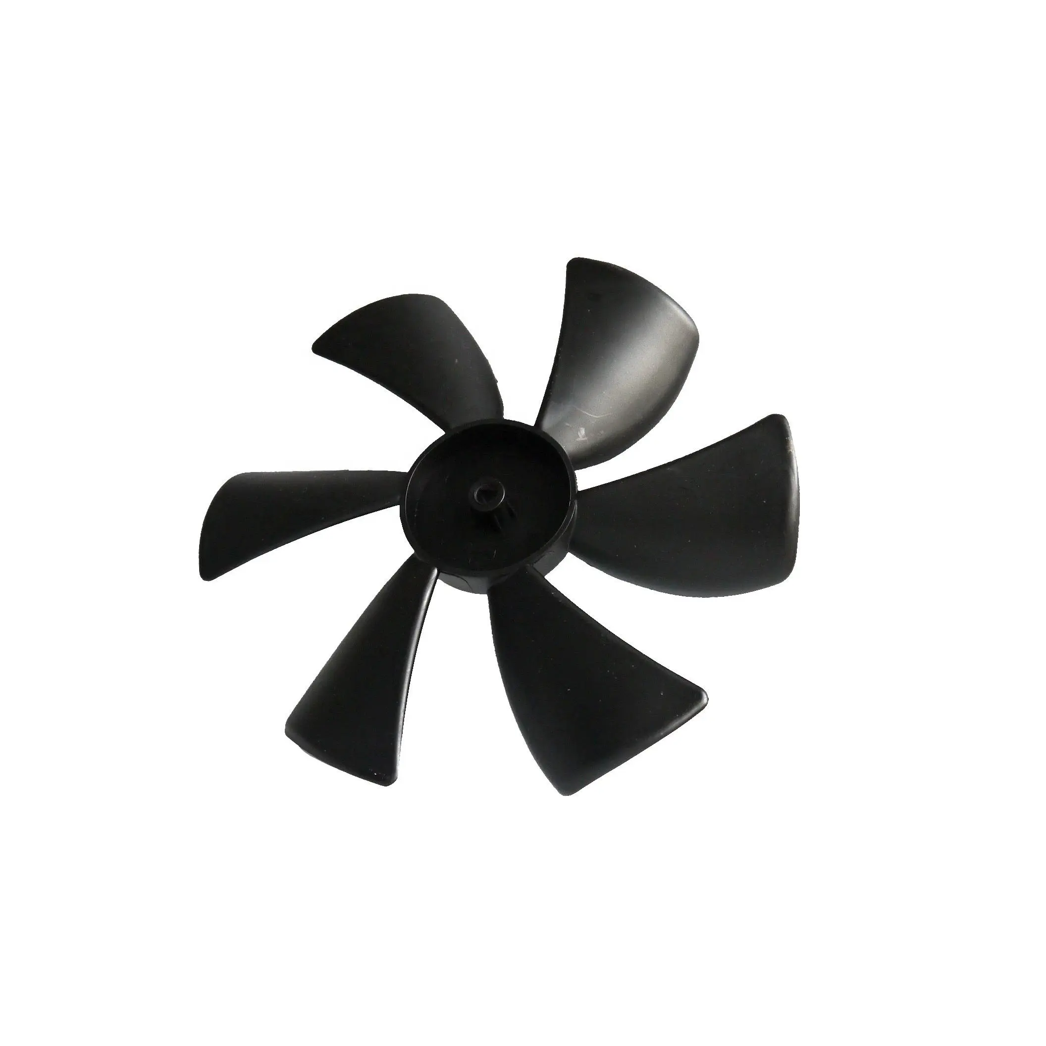
China Custom PA66-GF30 Injection Molded Motor Cooling Fan Blade | 6-Blade Axial Impeller Exporters, Factories
Product Description
⚙ Product Overview
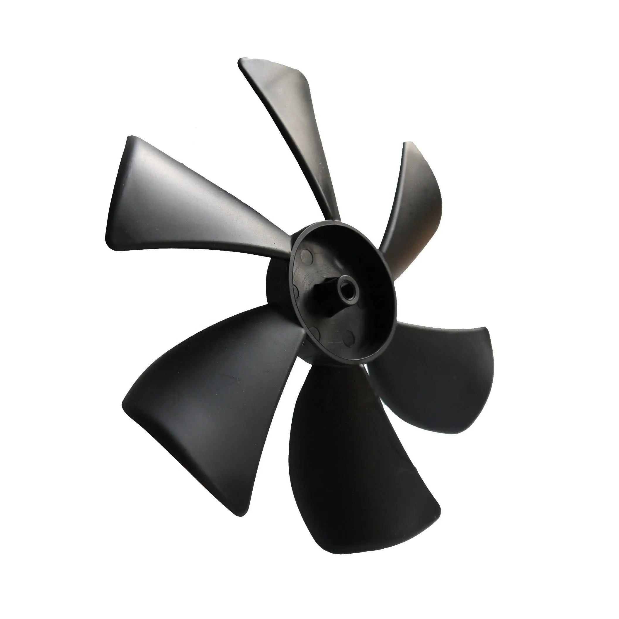
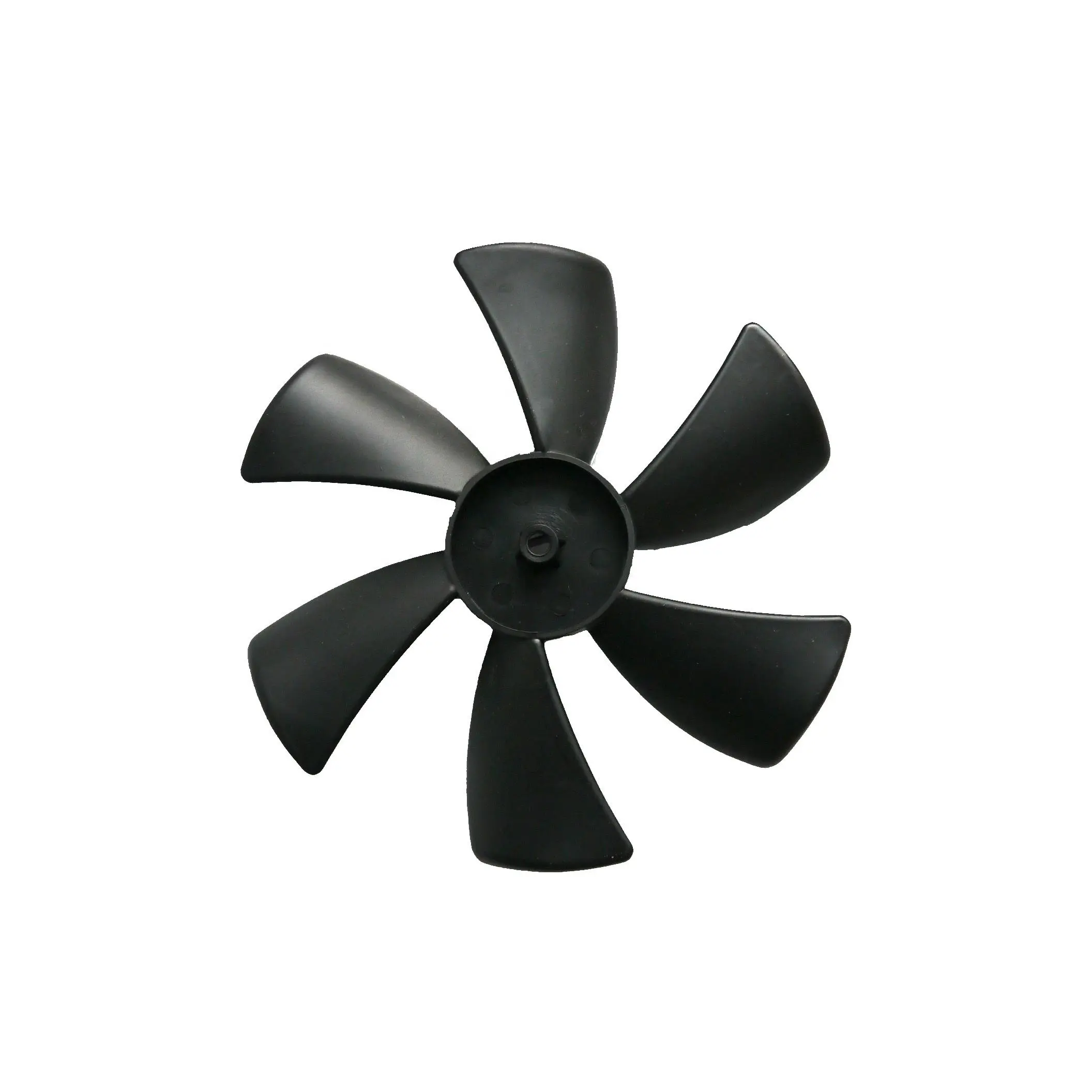
This custom six-blade axial motor cooling fan is an injection-molded component developed for airflow and heat-management applications in electric motors, BLDC assemblies, pumps, ventilation equipment, power tools, and industrial machinery. Its one-piece hub-and-blade structure can reduce assembly count while allowing the airflow geometry to be tailored to the motor package and installation space.
Based on customer drawings or samples, the outer diameter, blade count, blade pitch and curvature, hub bore, shaft interface, resin, color, and surface texture can be customized. PA66-GF30 is available when higher stiffness and dimensional stability are required; alternative engineering thermoplastics can be evaluated according to temperature, moisture, electrical, impact, and cost requirements.
🛠 Manufacturing Process & Technical Insights
At Shenzhen Sunmy Hardware Co., Ltd., the manufacturing route is defined around the customer drawing, operating conditions, target quantity, and inspection criteria:
- Tooling & DFM Review: Before mold manufacturing, we review blade-root thickness, hub geometry, draft angles, parting-line position, ejection, shrinkage allowance, and the accessibility of critical inspection features. Tool steel and cavity configuration are selected according to the resin, production volume, surface requirement, and mold-life target.
- Mold Filling & Gating Optimization: Gate position, runner balance, venting, packing, and cooling layout are evaluated to improve filling consistency across the blades and reduce risks such as short shots, weld lines, trapped air, warpage, and uneven shrinkage. Mold-flow analysis can be included when required by project complexity.
- Hub Geometry, Runout & Balance Control: The hub bore and blade geometry are controlled from the tooling stage through molding inspection. Critical dimensions, concentricity, and runout are verified against the approved drawing. Dynamic balance testing can be performed when specified, with acceptance grade and test speed defined by the customer application.
- Engineering Polymer Selection: Material is selected to match the actual operating environment. Typical options include PA66-GF30, other glass-filled nylons, PBT/PBT-GF, POM, PP, ABS, PC, and PC/ABS. Heat resistance, moisture absorption, impact, flame-retardancy, dimensional stability, and cost are reviewed before final material confirmation.
📋 Key Technical Specifications
| ENGINEERING PARAMETER | TECHNICAL SPECIFICATION & CUSTOM SCOPE |
|---|---|
| Product Designation | Custom PA66-GF30 Injection Molded Motor Cooling Fan Blade / 6-Blade Axial Impeller |
| Manufacturing Process | Precision Plastic Injection Molding; single-cavity or multi-cavity tooling according to volume |
| Impeller Configuration | 6-blade axial profile shown; blade count, pitch, curvature, and rotation direction can be customized |
| Engineering Materials | PA66-GF30, PA66, PBT/PBT-GF, POM, PP, ABS, PC, PC/ABS; final grade confirmed by application |
| Outer Diameter Range | Custom to customer 2D/3D drawing or approved sample; manufacturability confirmed during DFM review |
| Shaft Interface Options | Round bore, D-shaft, keyway, spline, press-fit interface, or insert-molded metal bushing as required |
| Hub Concentricity / Runout | Controlled to customer drawing and functional requirements; inspection method defined by criticality |
| Dynamic Balance Requirement | Dynamic balance inspection available when required; grade and test speed defined by project specification |
| Tooling Steel Options | S136, 718H, H13, NAK80 or equivalent tooling steels selected to resin, finish, and production volume |
| Tooling Lifespan | Defined by mold structure, resin, cavity count, maintenance plan, and target production volume |
| Surface Finish | Industrial matte, polished, textured, or customer-specified mold finish |
| Color / Appearance | Black, natural resin color, or custom color matching subject to material and project requirements |
| Operating Temperature | Dependent on the selected resin grade and real operating environment; confirmed during material review |
| Flammability Standards | Flame-retardant resin grades can be evaluated when required; certification level depends on selected material |
| Quality Inspection | Dimensional inspection, visual inspection, bore/runout checks, and balance testing when specified |
| Accepted Drawing Formats | STEP (.stp/.step), IGES (.igs), SolidWorks (.sldprt), Parasolid (.x_t), DWG, DXF, PDF |
| Tooling Lead Time | Quoted after drawing review; depends on part geometry, cavity count, resin, mold structure, and validation scope |
| Sample & Mass Production | T1 sample and production schedules are confirmed with the quotation after DFM and tooling evaluation |
★ Key Features & Competitive Advantages
The molded hub and curved blades form a single component, reducing secondary assembly while allowing the blade profile to be tuned around available space, airflow direction, and motor packaging requirements.
PA66-GF30 can provide higher stiffness and improved dimensional stability for suitable motor-cooling applications. Other polymers can be selected when moisture, impact, electrical insulation, appearance, or cost priorities differ.
Bore geometry, shaft fit, concentricity, runout, and balance criteria can be defined as critical-to-function characteristics and verified using the inspection method agreed for the project.
Where the hub requires higher torque transfer, wear resistance, or a dedicated shaft interface, brass, stainless-steel, or aluminum inserts can be evaluated for insert molding with retention geometry defined during DFM.
Sunmy can review the fan blade together with mating shafts, housings, brackets, and other custom components, helping OEM buyers coordinate injection molding with CNC machining, turning, casting, or stamping within one project supply chain.
❓ Technical FAQ for B2B International Buyers
📦 Other Products
✉ Get a Fast, Technical Quote & Free DFM Review
Don't let tolerance stack-up delay your product launch. Submit your project details, and our engineering team will evaluate your design for manufacturability before the first cut.