
Featured OEM Sheet Metal & Precision Components
Explore our certified hardware solutions, custom enclosures, and high-precision engineered structural assemblies.
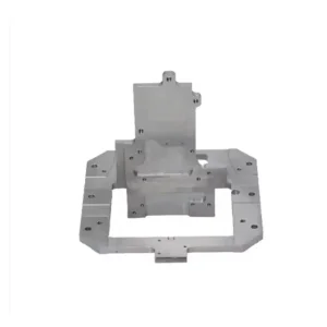
ODM High-Precision CNC Machined Metal Brackets & Structural Frames from China Suppliers - Wire EDM & Milling Factory for Aerospace & Automotive
View Component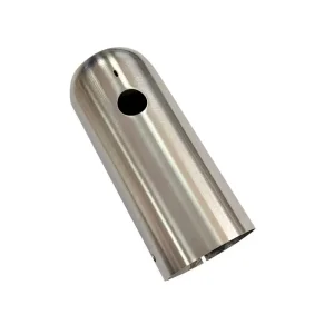
China Custom Precision CNC Turned Medical Sleeve Bushing Service, Exporters
View Component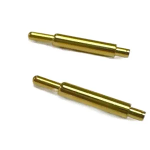
China Custom Gold-Plated Brass Pogo Pins - High Precision Connectors from China Suppliers & Factory for PCBs Manufacturer
View Component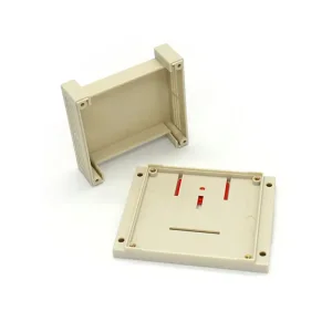
China Custom Modular DIN Rail PLC Enclosure Supplier, Exporter
View Component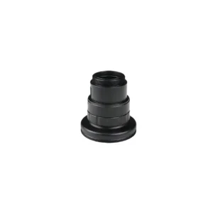
ODM Custom Precision CNC Turned Black Anodized Aluminum Lens Barrel & Optical Housing Components Manufacturer
View Component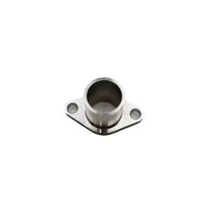
China Premium Custom Stainless Steel Casting Factory - Suppliers of Water Valves, Impellers, Pipe Fittings & Lugs
View Component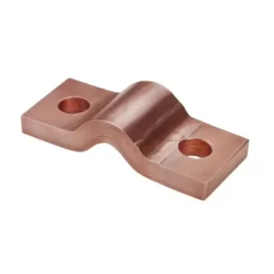
OEM Custom Flexible Laminated Copper Busbars for Battery & Electrical Equipment - China Factory & Suppliers
View Component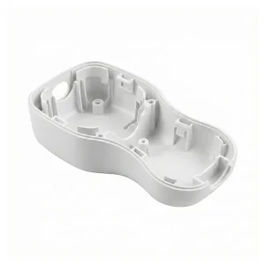
China Custom Medical Device Housing: Leading China Suppliers and Factory for High-Quality Solutions
View ComponentExecutive Summary: Navigating Modern OEM Sheet Metal Design
A comprehensive analysis of precision sheet metal engineering, Design for Manufacturability (DFM), and contract manufacturing paradigms.
In the contemporary landscape of global industrial manufacturing, OEM Sheet Metal Design represents a crucial convergence of mechanical engineering, material science, and cost-optimized production workflows. Sheet metal fabrication is no longer simply a process of cutting and bending plates; it has evolved into a highly digitized, automated discipline utilizing advanced CNC laser cutting, multi-axis press brakes, progressive stamping, and precision robotic welding. For Tier-1 procurement leaders, systems architects, and engineering executives, selecting an OEM manufacturer requires evaluate not just unit costs, but deep technical competence, Design for Manufacturability (DFM) support, material traceability, and robust quality assurance protocols.
This technical white paper establishes an exhaustive framework for evaluating OEM sheet metal designs, detailing structural integrity parameters, compliance requirements, tooling strategies, and supply chain dynamics. Through rigorous application of E-E-A-T (Experience, Expertise, Authoritativeness, and Trustworthiness) principles, this guide outlines actionable strategies for global enterprises looking to minimize total cost of ownership (TCO) while maximizing product lifespan and operational reliability across aerospace, automotive, medical device, telecommunications, and industrial equipment sectors.
Design for Manufacturability (DFM) Guidelines
Essential design parameters and physical constraints required to eliminate tooling rework and guarantee dimensional accuracy.
Achieving defect-free, repeatable production runs in sheet metal manufacturing hinges on strict adherence to DFM standards during the early conceptual phase. Ignoring geometry-specific bending behavior, hole clearances, and grain orientation leads to unwanted material stretching, localized fracturing, and costly tool re-engineering.
Core Geometric & Bending Calculations
The deformation zone along a bend undergoes simultaneous outer tension and inner compression. To maintain dimensional accuracy across flat pattern blanking, design engineers must compute the precise neutral axis repositioning via the K-Factor and Y-Factor equations:
Key Formula: K-Factor & Bend Allowance (BA) Calculation
K-Factor = t / T (where t is the distance from the inner surface to the neutral axis, and T is the total sheet thickness). Standard cold-rolled sheet metal generally exhibits a K-factor between 0.33 and 0.50 depending on tooling and material yield strength.
Bend Allowance (BA) = (π / 180) × A × (R + K × T)
Where A = Bend angle in degrees, R = Inside bend radius, and T = Material thickness.
Minimum Bend Radius
To avoid outer wall cracking, the inside bend radius (R) should equal at least 1.0x material thickness for ductile aluminum (5052-H32) and up to 2.0x for high-strength stainless steel (304/316).
Hole Distance to Bend
Pierced holes positioned too close to a bend line will deform under tension. Maintain a minimum clearance distance of D = 2T + R from the edge of the hole to the tangent line of the bend.
Bend Relief Slots
When a flange bends adjacent to flat material, side tearing occurs unless relief cuts are added. Relief slots must have a width greater than sheet thickness (T) and depth extending past the bend radius.
Grain Orientation
Bending parallel to the rolling grain of cold-rolled sheet increases the risk of micro-fracturing. Premium designs mandate bending perpendicular or at a 45° angle relative to the material grain direction.
Material Selection & DFM Parameters Matrix
| Material Alloy Standard | Tensile Strength (MPa) | Recommended Min. Radius (R/T) | K-Factor Range | Primary Industrial Applications |
|---|---|---|---|---|
| AL 5052-H32 (Magnesium Alloy) | 210 - 260 | 1.0 x T | 0.38 - 0.42 | Electronic enclosures, marine brackets, automotive panels |
| AL 6061-T6 (Structural Aluminum) | 290 - 310 | 1.5 - 2.0 x T | 0.40 - 0.45 | Aerospace frames, CNC structural brackets, thermal heat sinks |
| Stainless Steel 304 (Austenitic) | 515 - 620 | 1.5 x T | 0.42 - 0.47 | Medical equipment chassis, food-grade enclosures, cleanrooms |
| SPCC / SECC (Cold Rolled Steel) | 270 - 410 | 1.0 x T | 0.35 - 0.40 | Server rack cabinet structures, PDU strips, industrial controls |
| C1100 Copper (Econ-Grade Conductive) | 200 - 250 | 0.8 x T | 0.33 - 0.38 | Laminated flexible busbars, battery pack interconnects, power distribution |
Advanced Fabrication Techniques & Surface Finishing
Combining high-throughput CNC laser cutting, progressive stamping dies, and automated post-processing.
Modern OEM sheet metal production integrates multiple precise fabrication steps to move efficiently from raw stock to ready-to-assemble components. Selecting the right combination of cutting, forming, and surface finishing technologies directly affects both functional performance and long-term durability in field environments.
High-Precision CNC Blanking
Utilizing high-power Fiber Lasers (up to 20kW) and CNC Turret Punches to cut complex profiles down to ±0.05mm positioning tolerances. Laser cutting minimizes heat-affected zones (HAZ), eliminating burrs and thermal edge distortion.
Progressive & Deep Draw Stamping
For mid-to-high volume production runs (>10,000 units), multi-station progressive dies perform blanking, punching, coining, and forming in a single press stroke. Deep drawing forms seamless cylindrical and rectangular housings.
Precision Surface Treatment Options
Protect metal substrates against hostile field conditions with specialized post-treatments: Type II/III Hard Anodizing, Durability-rated Electrostatic Powder Coating, Passivation, Zinc/Nickel Plating, and Electrophoretic Deposition (E-coating).
China Factory Ecosystem: Strategic OEM Supply Chain Advantages
Leveraging deep industrial clusters, fast rapid-tooling turnaround, and unified engineering oversight.
Global enterprises sourcing OEM sheet metal designs increasingly lean on China’s mature industrial manufacturing ecosystems, particularly in high-density regions like Shenzhen and Dongguan. The primary competitive advantage extends far beyond base labor cost; it lies in the concentration of raw material suppliers, secondary surface finishing facilities, and specialized tooling shops operating within tight geographical radiuses.
Unmatched Tooling Speed
Rapid prototype dies and soft tooling completed in 5-7 working days. Hardened high-volume progressive stamping dies finalized in under 3 weeks, accelerating your overall time-to-market.
Single-Point Accountability
Integrated contract manufacturing covers blanking, CNC milling, precision stamping, custom plating, sub-assembly, and final testing under a single Purchase Order (PO).
Technical Engineering Support
Dedicated DFM reviews on every drawing within 24 hours. Bumper-to-bumper CAD analysis identifies tolerance stacks, reduces sheet scrap, and improves production yield.
Global Logistics Readiness
Full export-grade packaging with custom VCI anti-corrosion wrap, sea-worthy wooden crating, DDP/DAP freight coordination, and complete customs clearance documentation.
Global Procurement, IP Protection & Compliance Standards
Safeguarding enterprise intellectual property while verifying material and environmental regulatory compliance.
For multinational procurement teams, cross-border hardware manufacturing introduces supply chain risks related to Intellectual Property (IP) security, material non-compliance, and quality variance. Premier OEM sheet metal factories mitigate these risks through multi-layered legal, operational, and metrological protections.
Enterprise IP & NDA Protection
Strict data access restrictions are backed by legally binding Non-Disclosure Agreements (NDAs) before CAD drawing transfer. Engineering files remain isolated within secure internal networks, protecting client IP from unauthorized distribution.
RoHS, REACH & Conflict Minerals
Every raw sheet metal batch and surface plating finish is validated against EU RoHS Directive 2011/65/EU and REACH (EC 1907/2006) standards. Chemical analysis reports and mill test certificates (MTC) ship with every batch.
In-House CMM & FAI Documentation
First Article Inspection (FAI) reports following AS9102 standards are verified using 3D Coordinate Measuring Machines (CMM), optical laser scanners, and X-ray coating thickness gauges before full production sign-off.
Target Application Scenarios & Industry Use Cases
Engineered hardware designs tuned to the precise operational demands of major global sectors.
Automotive & EV Power Conversion
Custom flexible laminated copper busbars and battery pack enclosures designed for high current density, heat dissipation, and structural vibration isolation in electric vehicles.
Telecom & Server Rack Infrastructure
Precision modular DIN Rail PLC enclosures, 19-inch 1U-4U rackmount server chassis, and high-density PDU power strip housings crafted with EMI/RFI shielding protection.
Medical & Diagnostic Housings
Passivated stainless steel 316L and powder-coated aluminum medical equipment enclosures that meet strict hospital-grade sterilizability, chemical resistance, and cleanliness standards.
Future Trends: AI & Automation in Sheet Metal Engineering
How smart factories, digital twins, and generative design are reshaping the future of OEM manufacturing.
The sheet metal manufacturing industry is experiencing a profound transition driven by Smart Factory (Industry 4.0) initiatives. Algorithms and automated feedback loops are reducing traditional trial-and-error cycles during prototype tooling, ushering in a new era of ultra-efficient production.
Generative Design for Sheet Metal
AI-driven generative design algorithms automatically optimize part weight and rib layout while ensuring sheet metal bend feasibility, reducing mass by up to 30% without sacrificing strength.
Automated DFM Simulation
Instant cloud-based FEA stress modeling and springback prediction software simulate press brake bending beforehand, preventing springback errors in high-tensile steel alloys.
Robotic Bending & Laser Sorting
Fully autonomous cell integration with 6-axis robotic arms loading fiber laser tables and manipulating press brake sheets guarantees zero physical damage during high-volume runs.
Sustainable Green Manufacturing
Closed-loop scrap metal recycling and eco-friendly powder coating lines significantly reduce carbon intensity, helping corporate partners meet global ESG targets.
Frequently Asked Questions (FAQ)
Comprehensive engineering and procurement answers based on Search Intent Mining & Google Guidelines.
What key factors determine the cost of an OEM sheet metal fabrication project?
OEM sheet metal fabrication costs depend primarily on five variables: material selection (e.g., Stainless Steel 316L vs. SPCC), overall material utilization rate (nesting efficiency), part complexity (number of bends, formed louvers, or press inserts), tooling requirements (laser cutting for low volume vs. progressive stamping dies for high volume), and surface finishing options (anodizing, powder coating, or plating).
How do you control material springback during precision sheet metal bending?
Material springback occurs when elastic strain is released after the bending force is removed. We control springback by calculating precise material yield-to-tensile ratios, utilizing bottoming or coining techniques on CNC press brakes, applying digital over-bending adjustments based on lot-specific mill test reports, and designing stiffening ribs along bend lines to lock in the final geometry.
What standard dimensional tolerances can your factory achieve for sheet metal parts?
Our standard CNC laser cutting and punching tolerances conform to ISO 2768-m (Fine-to-Medium), maintaining linear dimensions within ±0.10mm. For critical CNC turned and post-machined features (such as bearing bores or sealed flange faces), we achieve tight tolerances down to ±0.01mm. Bending angle tolerances are controlled within ±0.5° across batch runs.
What CAD file formats are required to receive a fast engineering DFM quotation?
We accept standard 3D CAD formats, including STEP (.stp), IGES (.igs), and SolidWorks (.sldprt). To expedite tolerance verification and threading specifications, we also recommend providing vector 2D drawings in PDF or DXF/DWG format featuring fully dimensioned critical features, callouts, and material notes.
How do you guarantee quality consistency across high-volume production orders?
Quality control begins with raw material verification via Optical Emission Spectrometry (OES) upon arrival. During production, we conduct statistical process control (SPC) with inline operator inspections. Prior to final packaging, full dimensional validation is performed using CMM, optical comparator systems, and surface roughness testers, with First Article Inspection (FAI) reports included for auditing.
Explore Additional Custom Precision Components
High-volume custom hardware solutions engineered to meet demanding international OEM specifications.
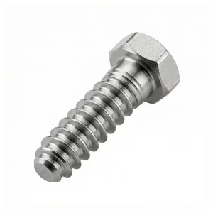
China Titanium Medical Implant Bone Screw - Precision Machining by Leading Suppliers and Factory Service
View Component
ODM Custom Black Anodized Aluminum Lens Barrel & Optical Housing Components | China Suppliers & Factory
View Component
ODM High-Precision Gold-Plated Brass Pogo Pins for PCB - China Factory Suppliers Custom Connectors
View Component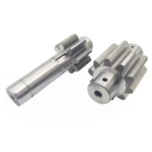
OEM Custom CNC Machined Spur Gears & Gear Shafts - Automotive Transmission Systems | China Suppliers
View Component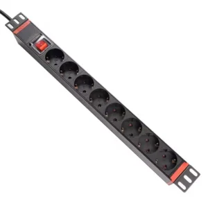
OEM Custom 8-Way German Standard 16A Rack-Mount PDU Power Strip (Sheet Metal Fabrication) Suppliers
View Component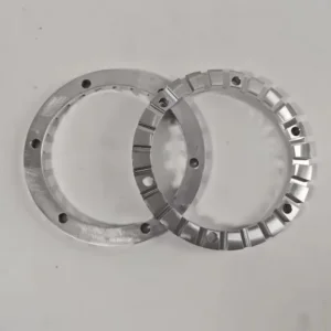
ODM Custom CNC Machined Anodized Sealing Rings for Semiconductor & Optical Instruments Suppliers
View Component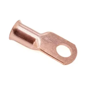
OEM Custom Tinned Copper Lug Ring Crimp Terminal Battery Wire Connector & Metal Stamping Brass Plug
View Component