ODM Custom Die-Cast Aluminum LED Luminaire Housing Manufacturers, Exporter
Product Description
Product Overview
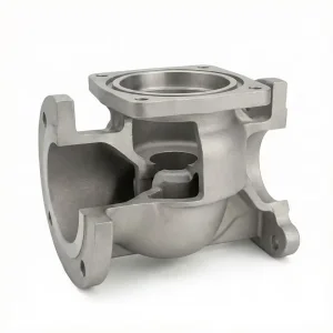
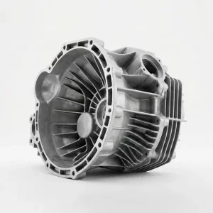
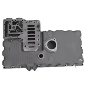
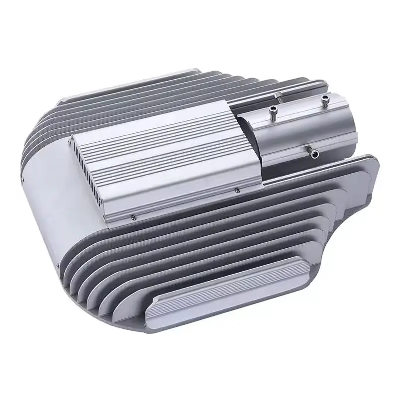
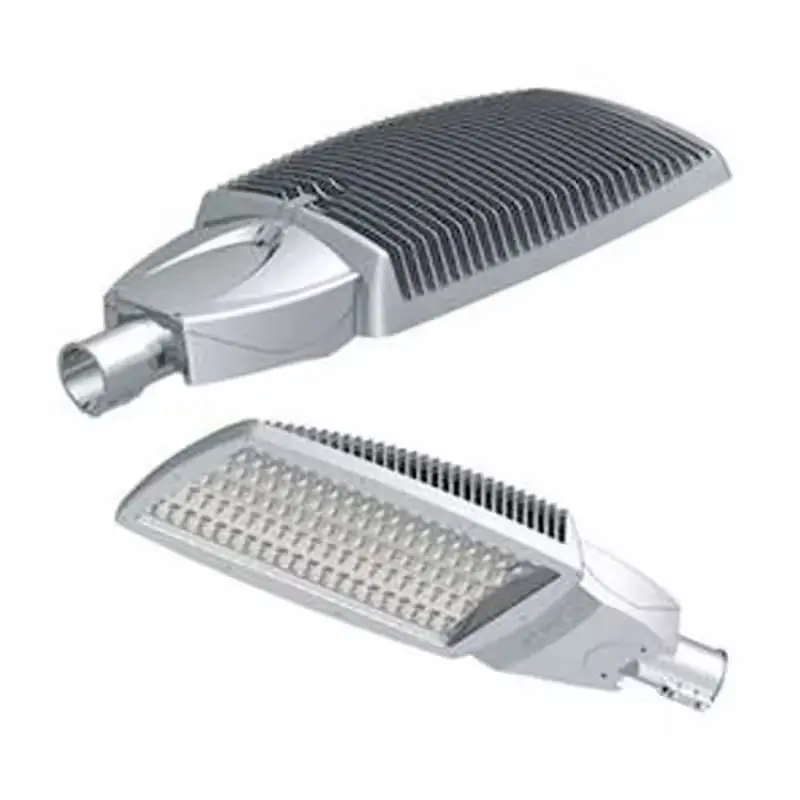
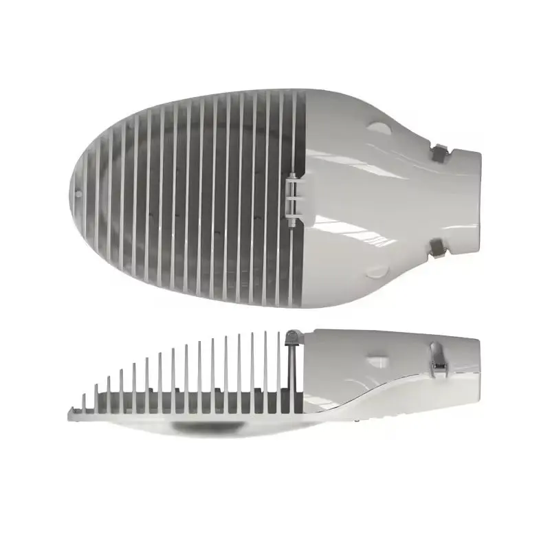
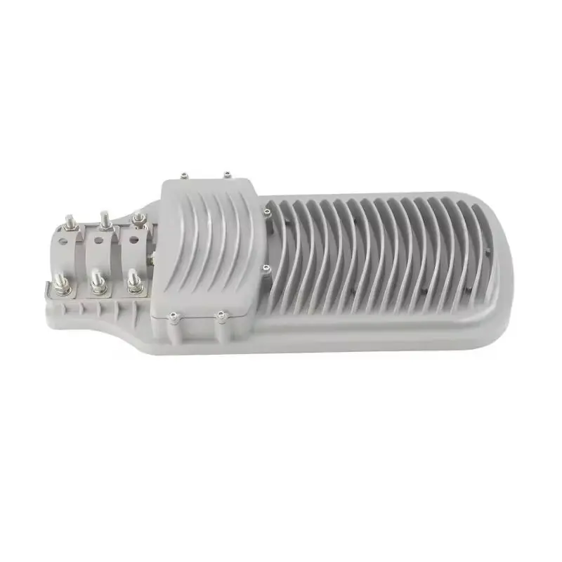
Shenzhen Sunmy Hardware Co., Ltd. supplies custom die-cast aluminum LED luminaire housings for municipal roadway lighting, highway installations, industrial floodlights and commercial perimeter fixtures. Depending on the approved design, the housing can combine cast-in cooling fins, separate optical and electrical compartments, machined lens interfaces and pole-mounting features. These are configurable features rather than a fixed, off-the-shelf luminaire specification.
Each housing is manufactured to customer-approved 2D drawings and 3D CAD data, combining high-pressure die casting, secondary CNC machining, finishing and agreed pre-assembly. Material grade, critical fits, sealing interfaces and inspection requirements are confirmed before production. Protection targets, coating durability and thermal acceptance criteria are set for the particular luminaire assembly and confirmed in the project scope.
Build-to-Print OEM/ODM Manufacturing
Sunmy coordinates DFM review, tooling, casting, CNC finishing, surface treatment and agreed sub-assembly through one project contact. The options below provide a basis for quotation and engineering review; they are not a fixed specification for every configuration. Final dimensions, performance targets, inspection scope, quantities and delivery dates are confirmed in the approved drawing and order.
Process & Manufacturing Insights
DFM review covers gate placement, runner layout, venting, overflow locations, wall transitions and fin filling. Press selection and tooling configuration are matched to the casting design and production quantity. Mold-flow analysis, where required, is defined in the tooling scope. The review identifies critical machined zones and casting-quality requirements. Porosity, filling and surface condition are evaluated against acceptance criteria agreed for the part.
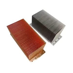
Cooling fins and the housing base can be cast as one component. Fin geometry, base thickness, LED module contact areas and driver-compartment layout follow the approved CAD model. Intended module power and thermal requirements should be supplied for review. Any required thermal validation is defined for the specified module and assembly conditions before a performance rating is agreed.
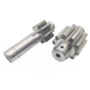
Secondary operations cover gasket grooves, lens-mounting planes, driver-tray standoffs, cable entries, mounting bores and fastener threads. Reference requirements include gasket-groove finish Ra 0.8–1.6 µm and mounting-plane flatness of 0.05 mm, subject to feature-specific review. Pole interfaces such as Ø48 mm, Ø60 mm or Ø76 mm are design options. Critical dimensions and thread requirements must be defined on the released drawing.
The finishing route may include shot blasting, degreasing, conversion pre-treatment and outdoor polyester powder coating. Powder manufacturer and product grade, film thickness, color and gloss are agreed for the order. An 80–120 µm dry film thickness is a reference option subject to coating-system review. Salt spray exposure, adhesion requirements and test reporting are agreed alongside the coating specification and approved finish sample.
Technical Specifications
| Technical Parameter | Reference Options / Project Requirements | Confirmation / Remarks |
|---|---|---|
| Product Name | Custom Die‑Cast Aluminum LED Luminaire Housing | Roadway and floodlight applications |
| Primary Manufacturing Process | High‑Pressure Die Casting (HPDC) + secondary CNC machining | Route agreed with tooling review |
| Aluminum Alloy Options | ADC12, A380, A383, AlSi10Mg or AlSi9Cu3 | Grade and condition confirmed before production |
| Dimensional Machining Tolerance | CNC reference: ±0.015 mm on designated features; as‑cast tolerances per drawing | Feasibility and datums confirmed per feature |
| Surface Roughness | Gasket‑groove reference: Ra 0.8‑1.6 μm; as‑cast fin texture by agreement | Validate with the specified gasket and assembly |
| Ingress Protection (IP Rating) | IP65, IP66 or IP67 as requested project targets | Supporting assembly test evidence required |
| Mechanical Impact Rating | IK08, IK09 or IK10 as requested project targets | Configuration and acceptance tests agreed |
| Thermal Conductivity | Confirmed for the selected alloy grade and condition | Use material data for thermal evaluation |
| Surface Treatment Options | Outdoor powder coating; shot blasting; anodizing subject to alloy and finish review | Powder brand and grade agreed before coating |
| Corrosion Resistance | Salt spray duration and acceptance to project specification | 1,000 h target where specified; evidence required |
| Color Options | RAL 7035, RAL 7040, RAL 9005 or customer‑specified color | Color and gloss sample approval |
| Mounting Spigot / Tenon | Reference interfaces: ∅48 mm, ∅60 mm or ∅76 mm | Clamp, fasteners and tilt per drawing |
| Secondary Machining Scope | CNC milling, drilling, tapping, boring and deburring | Operation and inspection plan per feature |
| Quality Assurance & Inspection | Dimensional, material and coating checks per inspection plan | FAI and special testing scope agreed at quotation |
| Customization Capability | Build‑to‑print using STEP, IGES, DXF, DWG or PDF | OEM / ODM project support |
| Tooling & Mold Lead Time | Indicative planning: 25‑35 working days | Scope and timing confirmed in tooling quotation |
| Sample Delivery (T1) | Indicative planning: 5‑7 working days after the agreed mold‑trial milestone | Sample status and report scope agreed |
| Mass Production Lead Time | Indicative planning: 15‑25 working days | Subject to volume, finish and production schedule |
| Minimum Order Quantity (MOQ) | Reference batches: 50‑100 pilot units; 500+ production units | Final batch quantities and MOQ agreed by project |
Key Features & Engineering Advantages
Cast-in fins, the thermal base and module mounting surfaces can be coordinated within one housing design. The buyer specifies the LED module layout, intended operating conditions and thermal acceptance criteria. This gives casting, machining and assembly teams a common basis for reviewing the thermal interfaces before tooling.
Gasket grooves, lens interfaces and closure features are manufactured to the approved drawing. Silicone or EPDM seals may be specified as part of the assembly. Requested ingress protection and production leak-screening are separate items in the approved inspection plan, with the relevant configuration and acceptance limits defined.
Wall transitions, reinforcing ribs, mounting bosses and clamp interfaces are reviewed against the project geometry. Required wind-load, vibration and impact performance must be defined and validated for the mounting arrangement. Test conditions and acceptance limits are agreed before samples are approved for production.
Separate optical and driver compartments, surge-protection mounting points and service-access features can be incorporated where required. Confirm the internal layout, clearances and screw-down or tool-free closure design before tooling. Early layout confirmation allows the casting, machining and assembly interfaces to be reviewed together.
Sunmy coordinates tooling, casting, machining, finishing and agreed sub-assembly through one project contact. The quotation defines supply scope, inspection documents and delivery milestones, giving buyers a clear basis for coordinating sample approval and repeat orders.
Technical FAQ for International Buyers
Q1: Can Sunmy Hardware produce the housing from our proprietary 3D CAD models?
A: Yes. Provide STEP/STP or IGES models together with PDF or DWG drawings showing critical tolerances, threads, sealing interfaces and finish requirements. Other file formats are checked for compatibility. Include quantities and mating-component information. DFM review covers draft, parting lines, wall thickness and machining allowances; review timing is agreed after the files are received.
Q2: Which aluminum alloy should be specified for an outdoor LED housing?
A: ADC12, A380, A383, AlSi10Mg and AlSi9Cu3 are listed as project options, not interchangeable materials. The grade is reviewed against casting geometry, mechanical requirements, finishing and the customer’s thermal specification. Thermal properties should come from data for the selected material. The final alloy and condition are confirmed before tooling and material procurement.
Q3: How are IP66/IP67 requirements handled during development and production?
A: State the required rating and closure design before tooling. Gasket interfaces, lens seating, fasteners and cable entries are included in the review. Assembly validation and production leak-screening requirements are agreed separately, with methods, sampling and acceptance limits recorded in the inspection plan. Supporting test evidence for the approved configuration defines the protection rating available for the supplied assembly.
Q4: What finishing information is needed for coastal installations?
A: Specify the exposure environment, substrate preparation, powder grade, film thickness, color and acceptance tests. AkzoNobel Interpon or Tiger Drylac may be nominated, subject to agreement on the exact product and availability. Salt spray duration and any requested corrosion classification require their own acceptance criteria and evidence; neither is inferred from a brand name or coating thickness alone.
Q5: What quality documents can be included with the order?
A: Agree the package at quotation: material identification or chemistry records, first-article dimensional results, coating thickness and adhesion reports, plus any specified salt spray, ingress or impact test reports. PPAP and specialist testing, when requested, require separate scope and feasibility confirmation. Specify required report formats and traceability needs before order placement so documentation can be planned with production.
Other products
Custom Modular Plastic Enclosures...
Custom Die Cast Aluminum Finned H...
Custom Injection Molded Electroni...
Custom Precision Sheet Metal Equi...
Get a Fast, Technical Quote & Free DFM Review
Don't let tolerance stack-up delay your product launch. Submit your project details, and our engineering team will evaluate your design for manufacturability before the first cut.