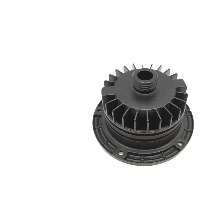
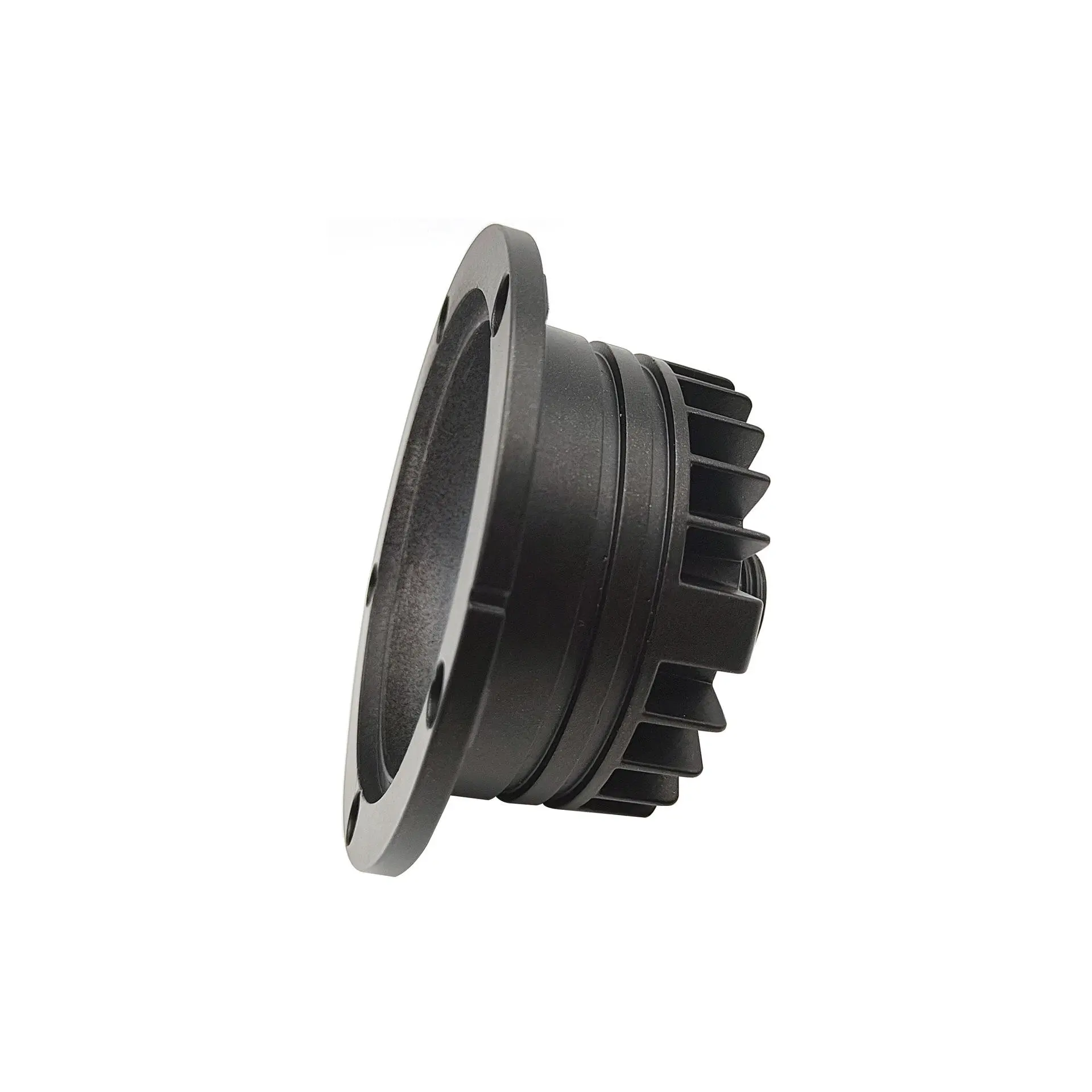
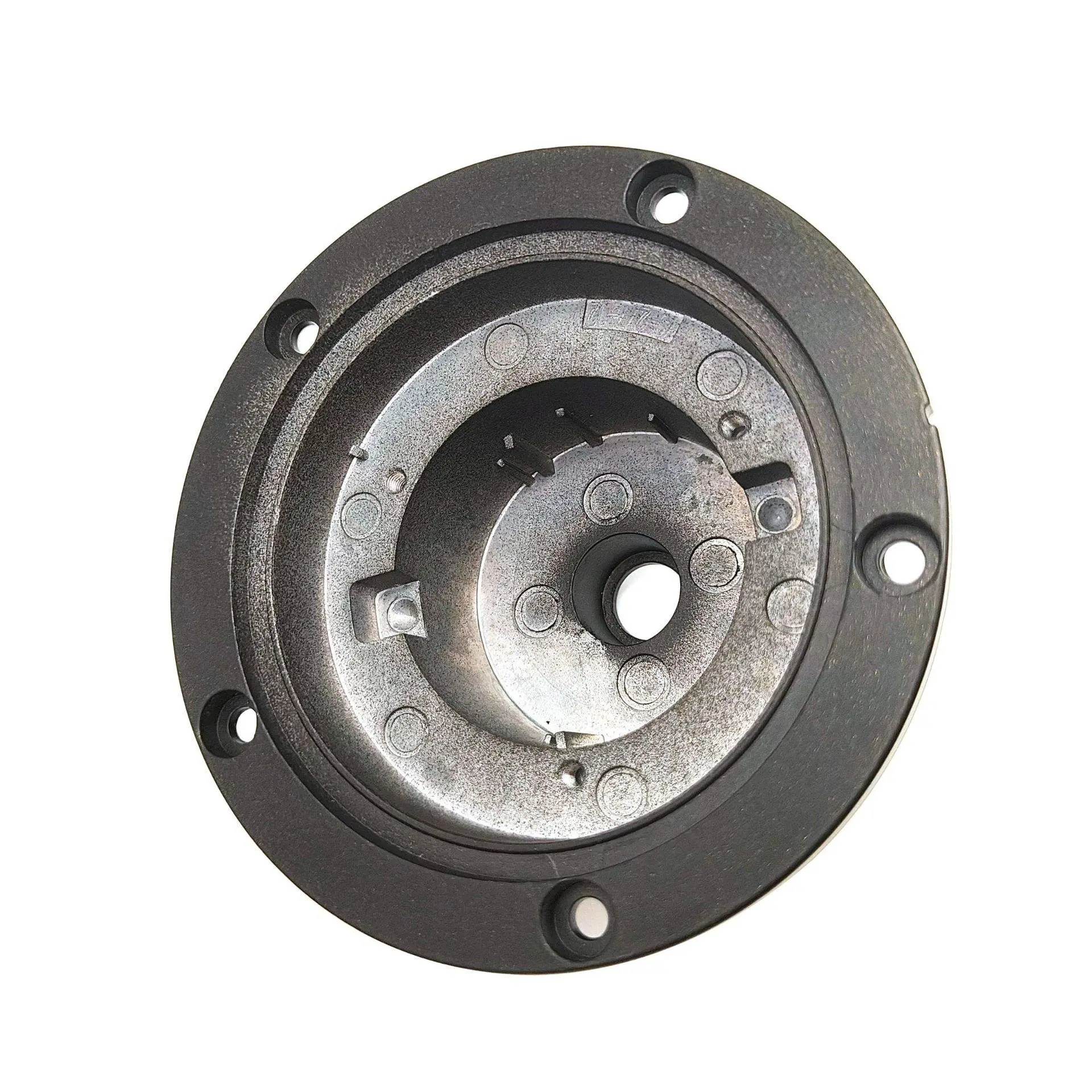
High-Quality Custom Die Cast Aluminum Finned Housings & End Caps Products, Quotes
Product Description
Product Overview
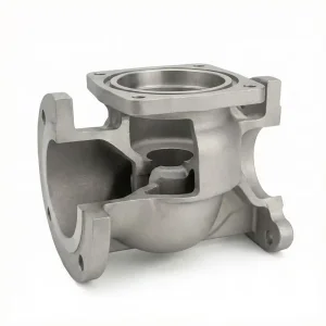
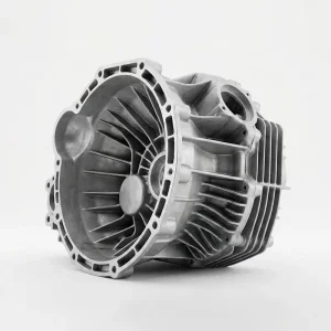
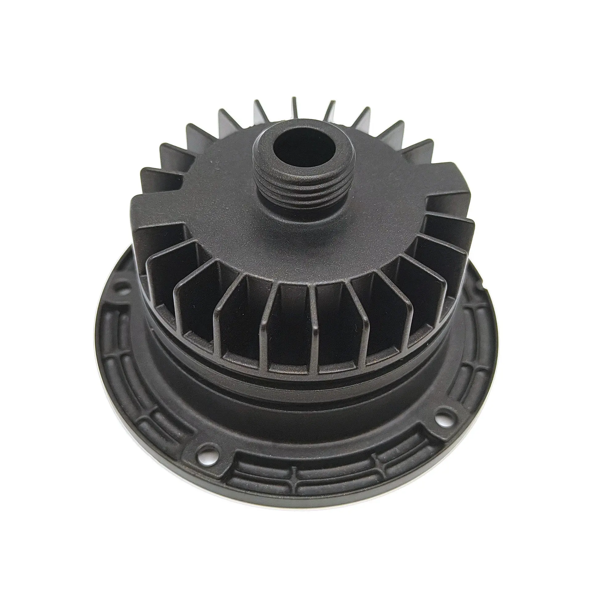
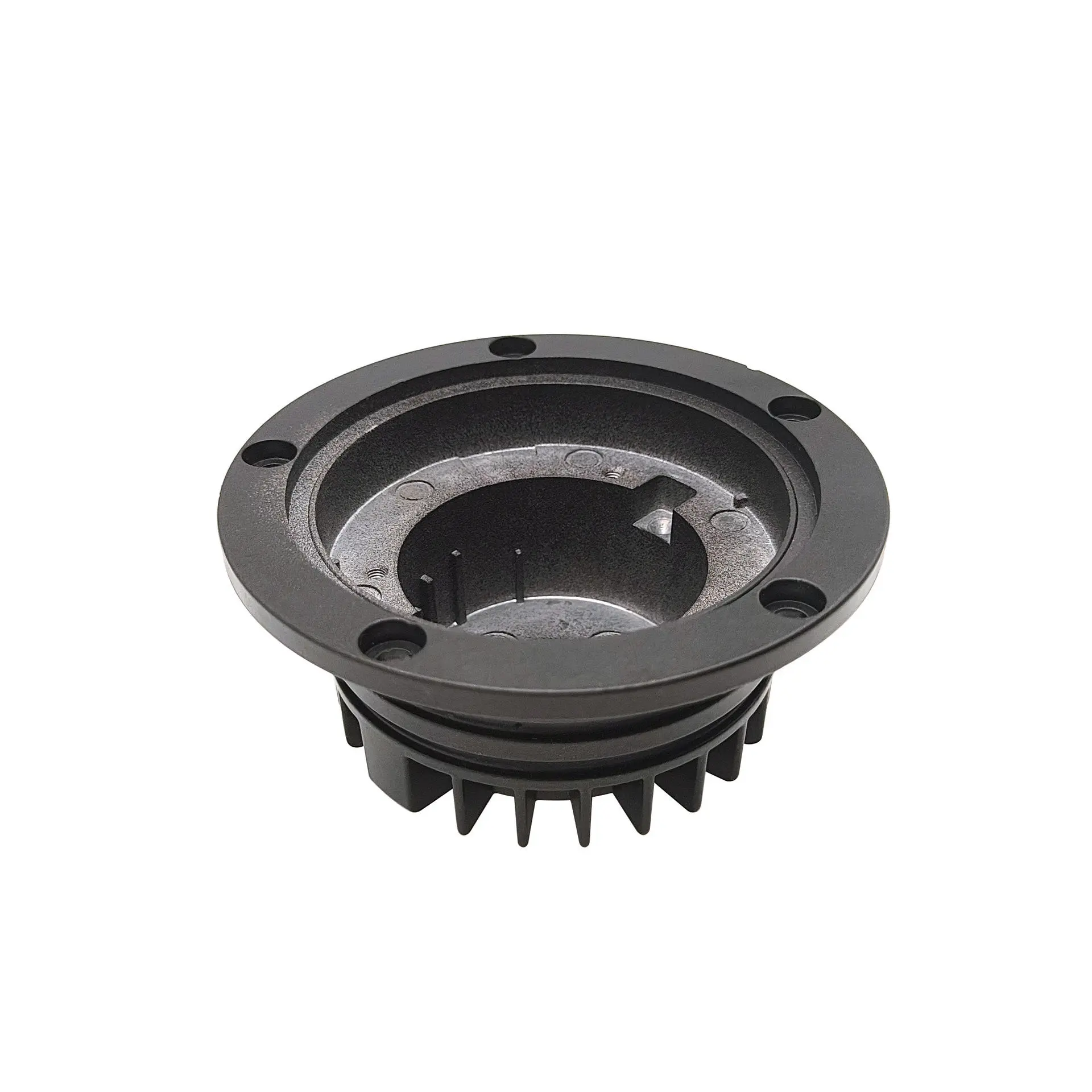
Keep your mounting layout. Customize the casting around it. Shenzhen Sunmy Hardware Co., Ltd. manufactures die-cast aluminum finned housings and end caps to customer drawings or samples, combining high-pressure die casting with secondary CNC turning and milling. Specify the flange, internal cavity, fitting diameters, groove profiles and threaded connections to suit your assembly. Supply can cover machined castings, coated housings or agreed mechanical subassemblies; motors, bearings, seals and electrical components are included only when listed in the quotation.
Manufacturing & Engineering Insights
One coordinated route from casting to finished part: review tooling, machining allowances, locating datums and coating boundaries before production. The approved drawing and inspection plan define the acceptance requirements.
Technical Specifications
| Parameter | Custom Options / Project Requirements |
|---|---|
| Product Name | Custom Die Cast Aluminum Finned Housing / End Cap |
| Manufacturing Process | High-Pressure Die Casting (HPDC) + CNC Turning, Milling, Drilling & Threading |
| Material Options | Aluminum: ADC12, A380, A360, AlSi9Cu3 or AlSi10Mg, subject to alloy/process review. Zamak 3/5 alternatives require separate design approval. |
| Tolerances & Fits | Casting grade and edition agreed per ISO 8062. CNC: ±0.01–0.02 mm reference targets on selected features. Bore fits and geometric limits specified separately. |
| Surface Roughness | Review targets: as-cast Ra 3.2–6.3 µm; machined Ra 0.8–1.6 µm; bearing seats Ra 0.8 µm where specified. Confirm by surface and process. |
| Surface Finishing | E-coating, powder coating, blasting or chemical conversion treatment. Anodizing subject to alloy suitability and sample approval. |
| Leak Testing & Ingress Protection | Grooves and mating faces to the selected seal. Leak-test criteria and any IP54/IP65/IP67 requirements use separately agreed procedures for the relevant assembly. |
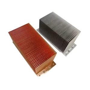
| Thermal Geometry | Fin count, spacing, height, thickness and airflow clearance customized to the drawing. Temperature rise and heat rejection verified in the intended assembly. |
| Critical Interfaces | Flange/pilot dimensions, bores or specified bearing seats, threaded boss, groove profile and mounting holes. Four- or six-hole patterns are examples, not limits. |
| Inspection & Documentation | Dimensional, thread and surface checks per agreed inspection plan. Sampling, FAI, material/coating records and required certification evidence confirmed at quotation. |
| Prototype & Tooling Schedule | Planning references: CNC fit-check samples 3–5 days; tooling and T1 cast samples 20–25 days. Confirm material, finish, trial scope and delivery schedule. |
| Production & Order Quantities | Reference production window: 15–25 days after approval. Pilot and repeat quantities, coating and inspection scope determine the confirmed schedule and order minimum. |
| Packing & Delivery | Protect fits, threads and coated faces with separators or EPE foam trays. Reinforced export cartons; pallets and additional protection as specified. |
Key Engineering Features & OEM Advantages
- Fin Geometry Matched to the Application: Adjust fin layout to the installation envelope, casting fill and available airflow. Thermal performance is evaluated with the actual heat source, mounting interface and environment, rather than inferred from the appearance or number of fins.
- Defined Fits, Not Blanket Precision: Datum-based machining and agreed gauges focus inspection on the interfaces that control assembly. A runout target below 0.015 mm can be reviewed for selected features. Bore size is controlled separately; motor noise and service life require assembly-level evaluation.
- Seal and Coating Decisions Made Together: Agree groove finish, masking, mating surfaces and test conditions before production. Quote bare castings, finish-machined housings and coated parts as distinct supply conditions so sample approval matches the production order.
- Ribs and Wall Sections to Suit the Design: Review wall thickness, reinforcement and machining stock against loads and tooling constraints. Evaluate proposed geometry changes before tool manufacture; prototype fit checks and production casting trials serve different approval purposes.
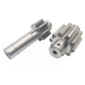
- Drawing-to-Part with Matching Components: Customize contours, fins, bores, flanges, threads and finishes from drawings or samples. Coordinate castings, turned fittings, stamped parts and molded components in one defined package. Send the housing drawing, mating-part details, material, finish and quantities for quotation.
Technical FAQ for Sourcing & Engineering Teams
Other Products
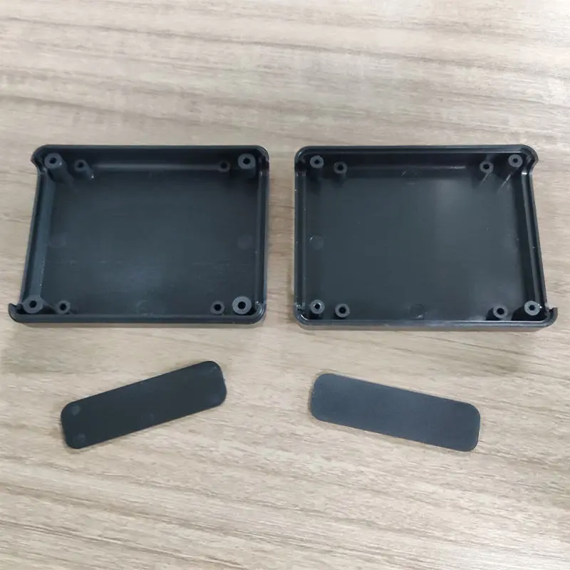
Custom Modular Plastic Enclosures
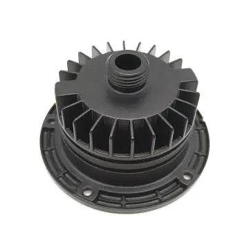
Custom Die Cast Aluminum Finned Housings
Custom Injection Molded Electronics Enclosure
Custom Precision Sheet Metal Enclosure
Get a Fast, Technical Quote & Free DFM Review
Don't let tolerance stack-up delay your product launch. Submit your project details, and our engineering team will evaluate your design for manufacturability before the first cut.