China Custom Die-Cast Aluminum Motor End Bell Housing Suppliers, Service
Product Description
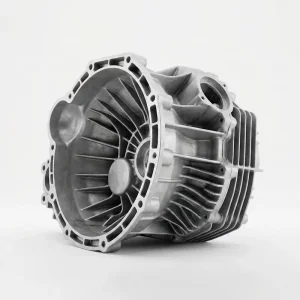
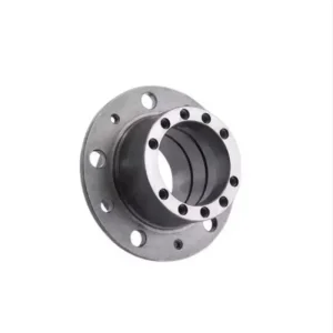
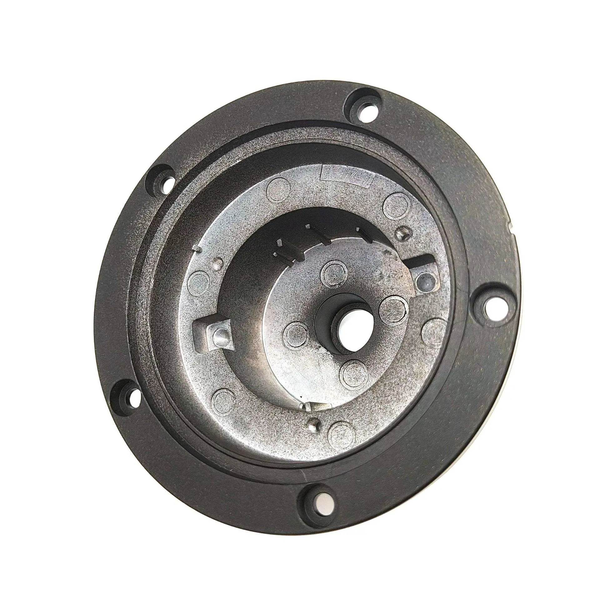
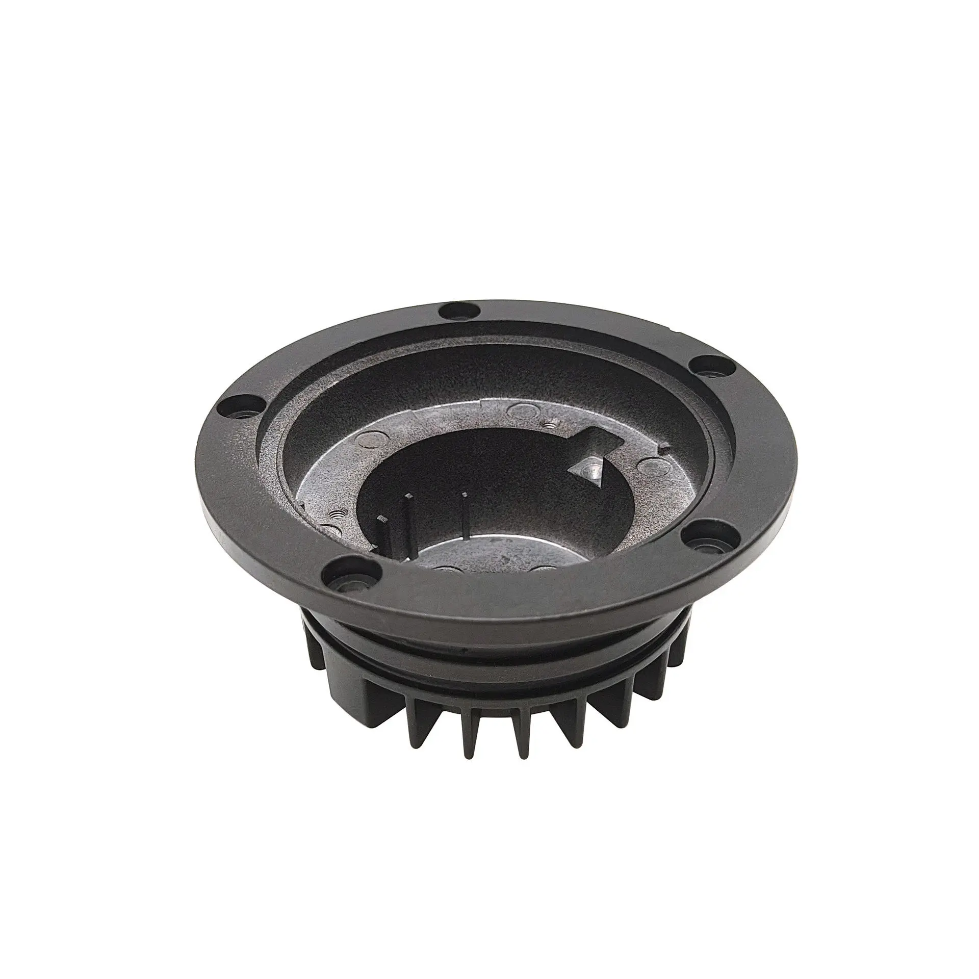
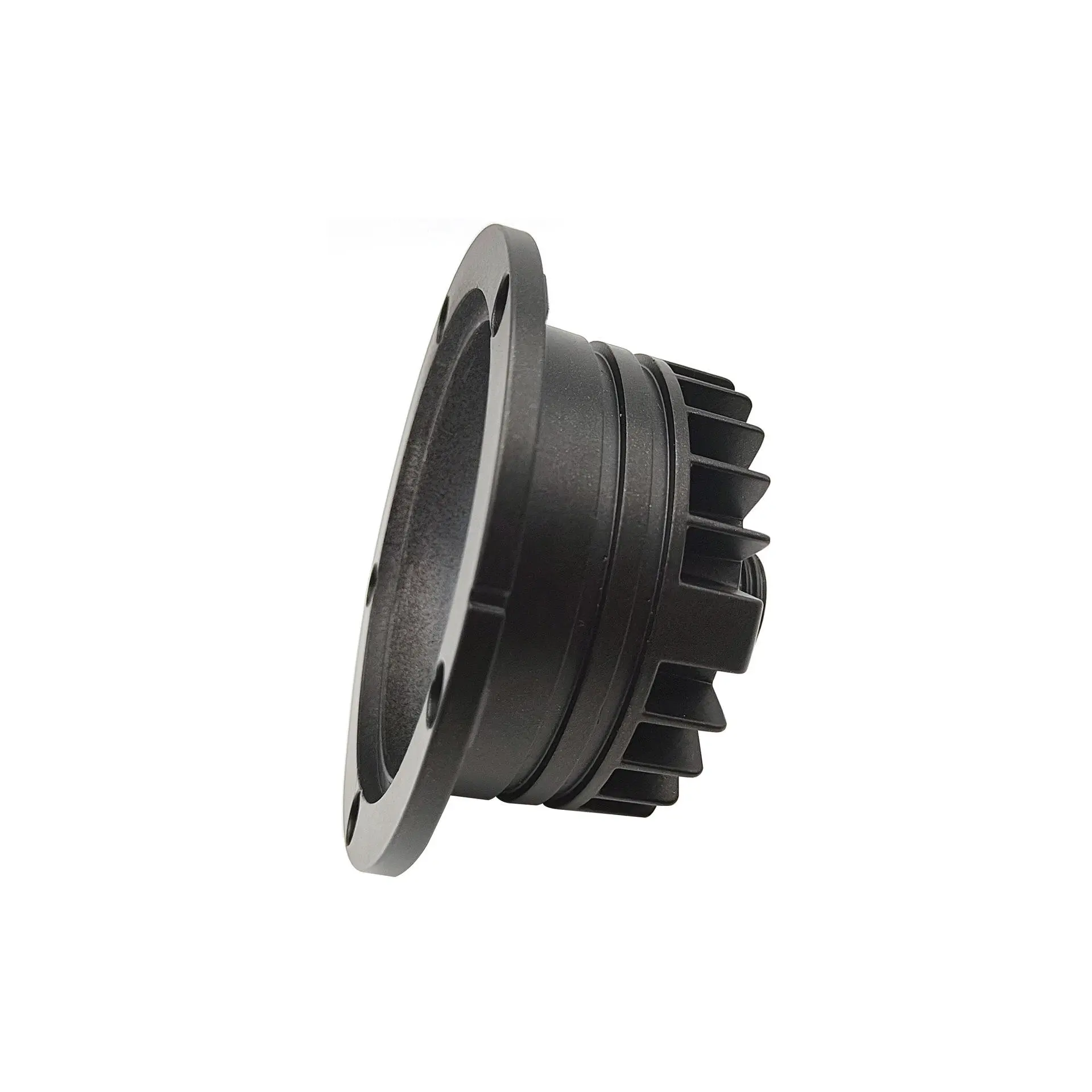
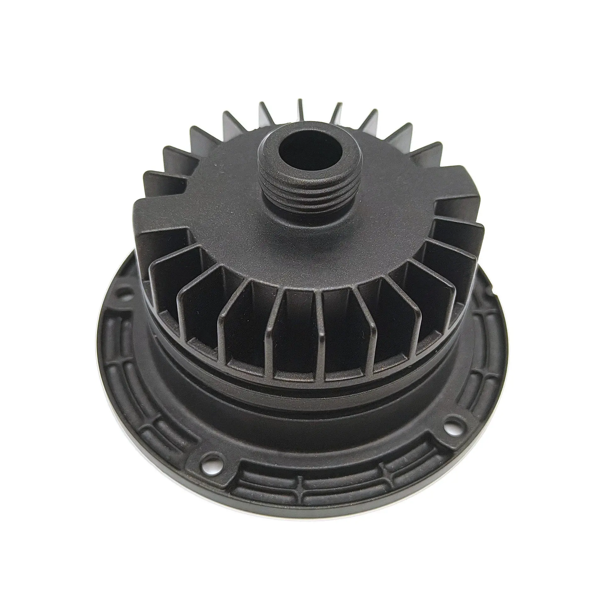
The Custom Die-Cast Aluminum Motor End Bell Housing is a configurable structural component for industrial electric motors, brushless DC (BLDC) motors, servo drives, pump motors, and actuator assemblies. The circular flange provides a stable motor-end mounting interface, while the integrated radial cooling fins increase external surface area to support heat dissipation around the motor and bearing zone.
The part is produced by aluminum high-pressure die casting (HPDC) with secondary CNC machining applied to critical interfaces such as the central bore or bearing seat, pilot diameter, flange face, mounting holes, and threaded features. Shenzhen Sunmy Hardware Co., Ltd. supports OEM/ODM customization from 2D/3D drawings or physical samples, including flange geometry, fin layout, hole pattern, machining datums, surface finish, and inspection requirements.
- Tooling & DFM Review: Before tooling, the engineering review focuses on wall thickness, draft angles, radial fin geometry, gate/overflow/vent locations, machining allowance, and the position of critical bearing and mounting features. Flow simulation can be used when required to evaluate filling behavior and reduce avoidable casting risks before mold release.
- High-Pressure Die Casting (HPDC): Aluminum die-casting alloys such as ADC12, A380, A360, or equivalent grades can be selected according to the drawing, mechanical requirements, surface finish, and production volume. HPDC is well suited to integrating the circular flange, housing body, ribs, and radial cooling fins into a repeatable near-net-shape component.
- Precision Secondary CNC Machining: After casting, functional datums and interfaces can be finish-machined by CNC turning and milling. Typical operations include boring the central bearing or shaft interface, facing the mounting flange, machining pilot diameters, drilling or countersinking mounting holes, and producing threaded bosses or ports to the approved drawing.
- Surface Finishing: Trimming, deburring, shot blasting, tumbling, and protective coatings can be specified according to the application. The product shown uses a matte black finish; powder coating is a common option, while other finishes are reviewed according to alloy compatibility, corrosion targets, and cosmetic requirements.
- Quality Verification: Dimensional inspection is carried out against the approved drawing and critical datum scheme. CMM inspection can be used for key GD&T characteristics, with material verification, coating checks, X-ray inspection, or leak testing added when they are specified in the RFQ and agreed inspection plan.
| Technical Parameter | Engineering Specifications & Capabilities | Customization Scope |
|---|---|---|
| Product Name | Custom Die-Cast Aluminum Motor End Bell Housing | Customized design based on motor assembly and mounting requirements |
| Primary Process | High-Pressure Die Casting (HPDC) + Secondary CNC Turning & Milling | Adjust machining operations and casting gating system upon DFM review |
| Material Options | Die-casting aluminum alloys such as ADC12, A380, A360, AlSi9Cu3, or equivalent grades selected to application requirements | Alternative casting alloys evaluated according to thermal, mechanical and cost targets |
| Casting Tolerance | Defined by part geometry and drawing requirements; ISO 8062-3 can be applied when specified | Casting draft, shrinkage and parting line tolerances confirmed at DFM stage |
| CNC Machining Tolerance | Critical bearing, pilot, flange, hole, and threaded features machined to drawing; tighter tolerances reviewed during DFM | Tolerance stack-up analyzed for bearing fit and mating interface performance |
| Concentricity & Flatness | Controlled according to the functional datum scheme, mating-part requirements, and approved drawing | Datum targets and CMM inspection plan agreed before tool release |
| Dimensional Range | Fully customized to customer drawing or sample; feasibility confirmed after DFM and tooling review | Part size, wall thickness and undercut features assessed for die cast feasibility |
| Heat Dissipation Design | Integrated radial cooling fins; fin count, pitch, thickness, height, and draft can be customized | Thermal simulation review available for fin geometry optimization |
| Connection & Mounting | Perimeter mounting holes, central bore/bearing interface, pilot diameter, and threaded boss or port as specified | Custom boss locations, hole patterns and quick-fit interfaces supported |
| Surface Treatment | Deburring / shot blasting; matte black powder coating shown; other finishes evaluated by alloy and application | Anodizing, chromate conversion or other coatings reviewed for cast aluminum compatibility |
| Corrosion Resistance | Coating and salt-spray requirements can be defined in the RFQ and verified to the agreed test specification | Custom salt spray test duration and acceptance criteria negotiable |
| Quality & Testing | Dimensional inspection, CMM for critical GD&T, material verification; X-ray or leak testing when specified | Custom test plan developed based on safety and application risk level |
| Quality Documentation | FAI/FAIR, dimensional reports, material certificates, and coating/test records available as agreed | PPAP documentation support available upon project requirement |
| Prototyping & Production | CNC prototype or pilot sample options available before tooling; tooling and production lead times quoted per project | Separate timeline for prototype, tool build and mass production phases |
| MOQ & Capacity | Prototype, pilot, and volume production supported; MOQ depends on tooling, geometry, alloy, and annual demand | Annual volume and batch scheduling optimized for cost and delivery |
| Supported File Formats | STEP (.step, .stp), IGES (.igs), SolidWorks (.sldprt), DXF, DWG, PDF | Please provide 2D drawing with tolerances, GD&T and surface finish notes |
- Integrated Radial Cooling Fins: The cast-in fin array increases external surface area around the motor-end structure and can support improved passive or forced-air heat transfer. Fin count, spacing, thickness, and draft are adjustable to the customer design and casting feasibility.
- One-Piece Die-Cast Structure: The flange, housing body, ribs, and cooling features can be consolidated into one casting, reducing the need for separate fabricated pieces and helping simplify downstream assembly and dimensional stack-up.
- Precision-Machined Functional Interfaces: Bearing seats, shaft or pilot bores, flange faces, mounting holes, and threaded features can be CNC finished after casting so the critical interfaces are controlled independently from the as-cast surfaces.
- Configurable Mounting & Interface Geometry: Bolt-circle diameter, hole size, flange thickness, central bore, locating pilot, threaded boss, and other interface features can be customized to the mating motor frame, gearbox, pump, or actuator assembly.
- OEM DFM & Multi-Process Support: Sunmy Hardware can coordinate drawing review, tooling, die casting, CNC post-machining, surface finishing, inspection, and production release as one project. Final process steps are selected according to function, volume, tolerance, and cost targets.
Custom Modular Plastic Enclosures...
Custom Die Cast Aluminum Finned H...
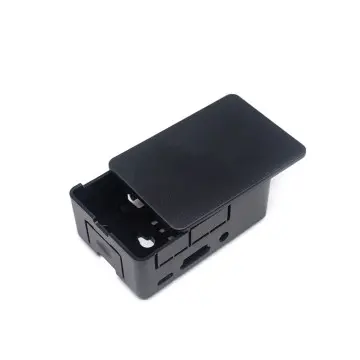
Custom Injection Molded Electroni...
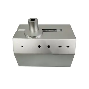
Custom Precision Sheet Metal Equi...
Don't let tolerance stack-up delay your product launch. Submit your project details, and our engineering team will evaluate your design for manufacturability before the first cut.